Control device for vehicular automatic transmission

a technology of control device and automatic transmission, which is applied in the direction of mechanical equipment, instruments, etc., can solve the problems of following problems, turbine blow-up, etc., and achieve the effect of suppressing the extended quickening of shifting response, preventing the delay of hydraulic pressure response, and quickening the shifting respons

Active Publication Date: 2010-03-04
TOYOTA JIDOSHA KK
View PDF17 Cites 3 Cited by
  • Summary
  • Abstract
  • Description
  • Claims
  • Application Information

AI Technical Summary

Benefits of technology

[0013]Preferably, the extent of quickening of the shifting response is suppressed during the shifting related to at least one gear position where the response of the hydraulic pressure control executed by the hydraulic pressure control circuit fails to satisfy the preset predetermined determining criterion, compared with during the shifting related to entire gear positions where the response satisfies the determining criterion. With such structure or operation, a driver's uncomfortable feeling caused by the high-response shifting being permitted for a predetermined shifting is inhibited for the other shifting, can be properly prevented.
[0014]Preferably, the control device for the vehicular automatic transmission further comprises a shift operation device operative to perform a manual shifting of the automatic transmission depending on a driv

Problems solved by technology

However, when performing the control which requires a response in hydraulic pressure related to the shifting, like a high-response shifting in a clutch-to-clutch shift in the conventional technology described above, following

Method used


Image

  • Control device for vehicular automatic transmission
  • Control device for vehicular automatic transmission
  • Control device for vehicular automatic transmission

Examples


embodiment

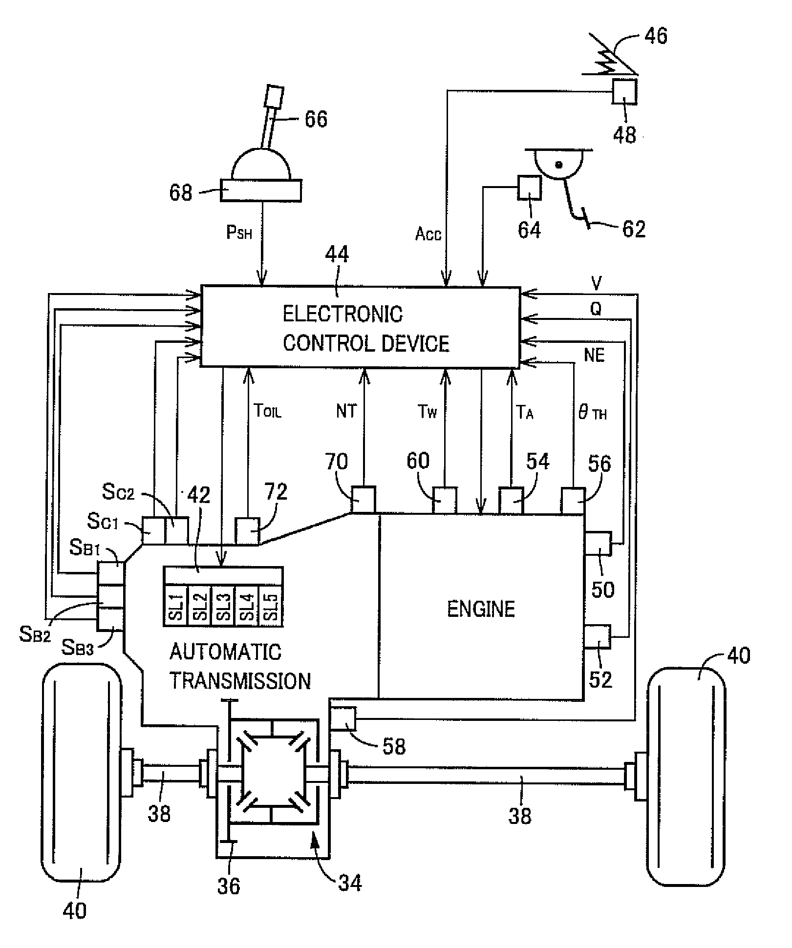
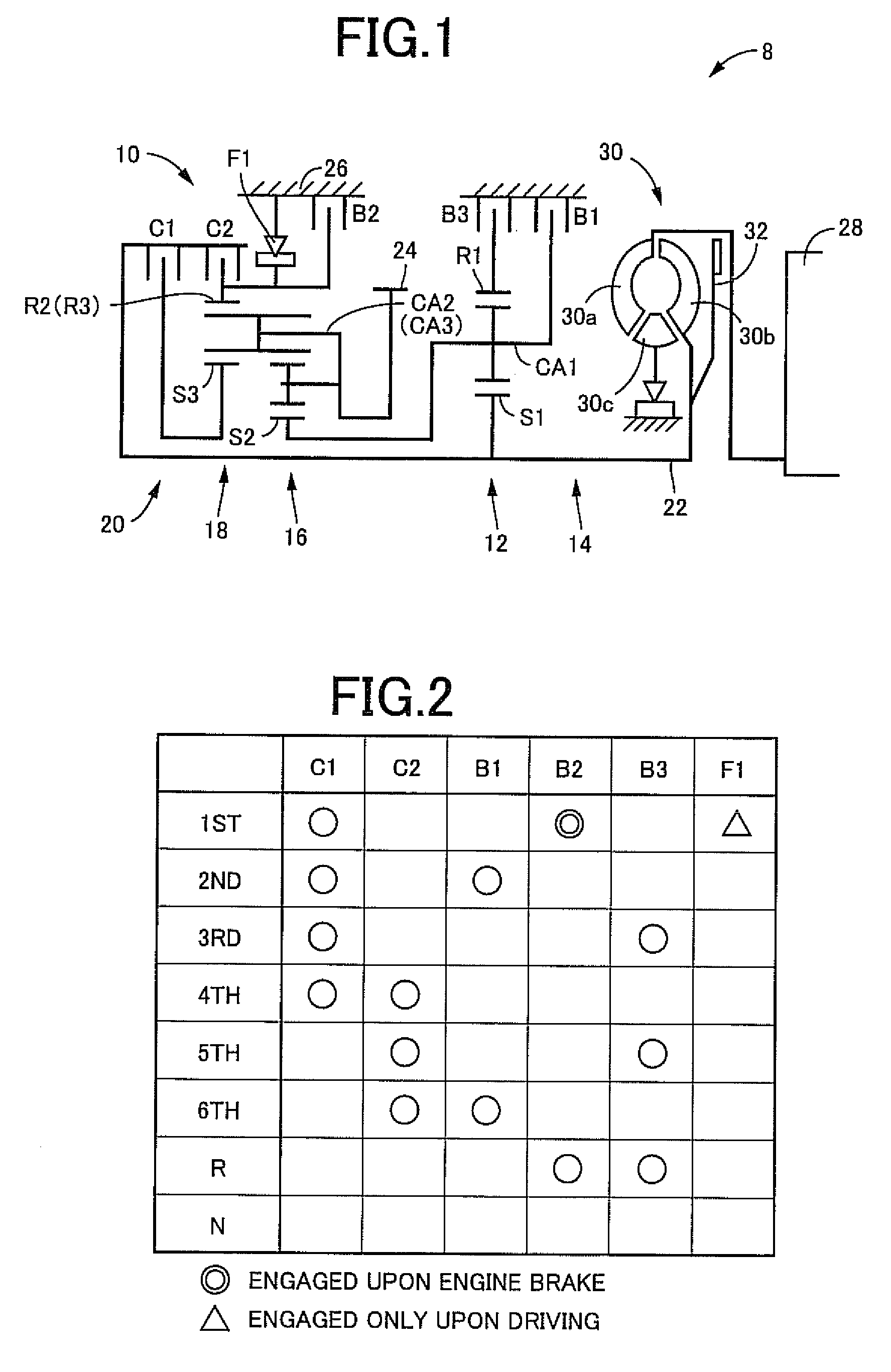
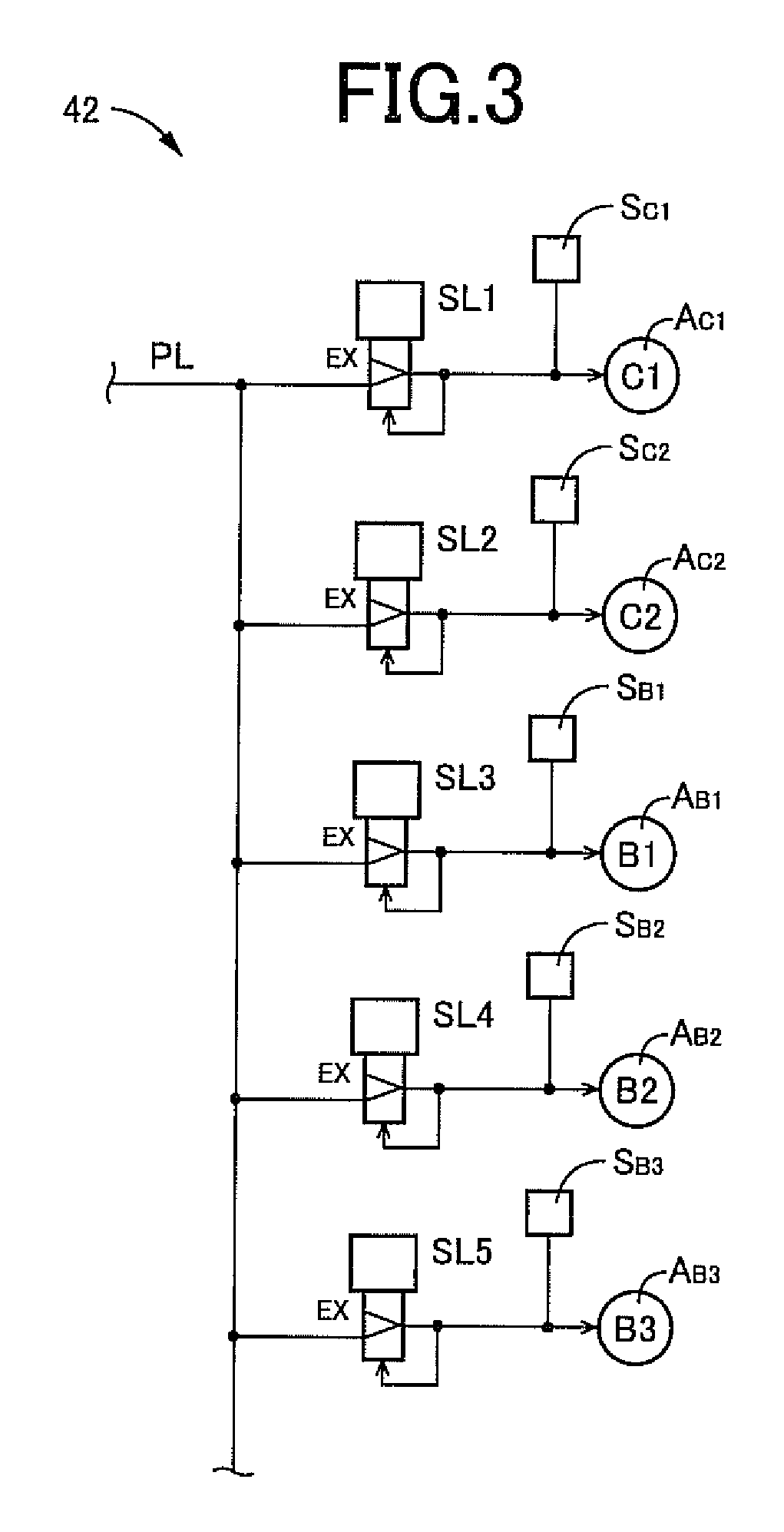
[0029]FIG. 1 is a skeleton view of a power transfer apparatus 8 to which the present invention is preferably applied. FIG. 2 represents an operation table illustrating operating states for engaging elements to be actuated for establishing a plurality of gear positions in a vehicular automatic transmission 10 (hereinafter merely referred to as a “transmission”) incorporated in the power transfer apparatus 8. The transmission 10 is of the type that is preferably applied to an FF vehicle or the like to be installed on a vehicle in a lateral direction thereof (under a transverse state). The transmission 10 includes a first shifting portion 14 mainly comprised of a first planetary gear set 12 of a single pinion type, and a second shifting portion 20 mainly comprised of a second planetary gear set 16 of a double pinion type, and a third planetary gear set 18 of a single pinion type that are formed in a Ravigneaux type. The first and second shifting portions 14 and 20 are coaxially dispose...


PUM


Abstract

A control device for a vehicular automatic transmission which can realize a shifting with quickened response with suppressing a turbine blow-up during the shifting is provided. When a response in hydraulic pressure control by a hydraulic pressure control circuit 42 fails to satisfy a preset predetermined determining criterion, a shifting response is prevented from improving, in comparison to a case where the determining criterion is satisfied. Under a relatively low response of the hydraulic pressure control by the hydraulic pressure control circuit 42 due to air mixture to working oil, a control to inhibit a high-response shifting or the like is performed, so that a turbine blow-up caused by a delayed response of hydraulic pressure can be prevented. Thus, the control device for the vehicular automatic transmission can be provided, which can realize the shifting with quickened response, with suppressing the turbine blow-up during the shifting.

Description

[0001]This invention is based on Japanese Patent Application 2008-226473 filed on Sep. 3, 2009, and content thereof is incorporated herein for reference.TECHNICAL FIELD[0002]The present invention relates to control devices for vehicular automatic transmissions and, more particularly, to an improvement to realize a shifting with a favorable response with suppressing a turbine blow-up during the shifting.BACKGROUND ART[0003]There has been known a control device for a vehicular automatic transmission of the type including a plurality of hydraulically operated engaging elements and a hydraulic pressure control circuit arranged to control hydraulic pressures supplied to the plural hydraulically operated engaging elements. A shifting response is varied based on a preset relation depending on a predetermined condition. For instance, Patent Publication 1 (Japanese Patent Publication No. 9-79365) discloses a control device for a vehicular automatic transmission. With such a technology, in a ...

Claims


Application Information

Patent Timeline
IPC IPC(8): G06F19/00F16H59/10F16H59/18F16H59/44F16H59/72F16H61/04F16H61/68F16H61/684F16H61/686
CPCF16H61/061F16H2061/004Y10T477/6939Y10T477/6243Y10T477/624Y10T477/648F16H2061/0477
Inventor OTA, KEISUKEMATSUNAGA, HITOSHIOSHIMA, KOJI
Owner TOYOTA JIDOSHA KK
Why Eureka
Try Eureka