
Apparatus for generating a current in a pool

a technology for generating currents and apparatuses, applied in the direction of sports apparatus, liquid fuel engines, non-positive displacement pumps, etc., can solve the problems of requiring separate mountings for intake and outlet pipes and for pumps, and achieve the effect of increasing volum

Inactive Publication Date: 2010-03-11
CLAREY MICHAEL
View PDF2 Cites 14 Cited by
  • Summary
  • Abstract
  • Description
  • Claims
  • Application Information

AI Technical Summary

Benefits of technology

"The invention is an apparatus for generating a current in a liquid-containing vessel for swimming against. The apparatus includes a shell with an intake chamber and a pump. The intake chamber has a suction-side inlet and a discharge-side outlet. The pump has a drive shaft with a suction-side end wall and a discharge-side end wall. A guide means is used to direct liquid flow through the intake chamber. The apparatus allows for a high volume of liquid to be delivered to the exercise zone with low velocity and low turbulence. The intake chamber has a large volume to allow for a low velocity liquid flow. The apparatus is safer and reduces the likelihood of sucking objects onto or through the intake zone. The technical effects of the invention include improved current generation, reduced losses, and improved safety."

Problems solved by technology

This type of apparatus, however, suffers from the disadvantage that separate mountings for the intake and outlet pipes and for the pump are required to be made in the swimming pool.

Method used


Image

  • Apparatus for generating a current in a pool
  • Apparatus for generating a current in a pool
  • Apparatus for generating a current in a pool

Examples


Embodiment Construction

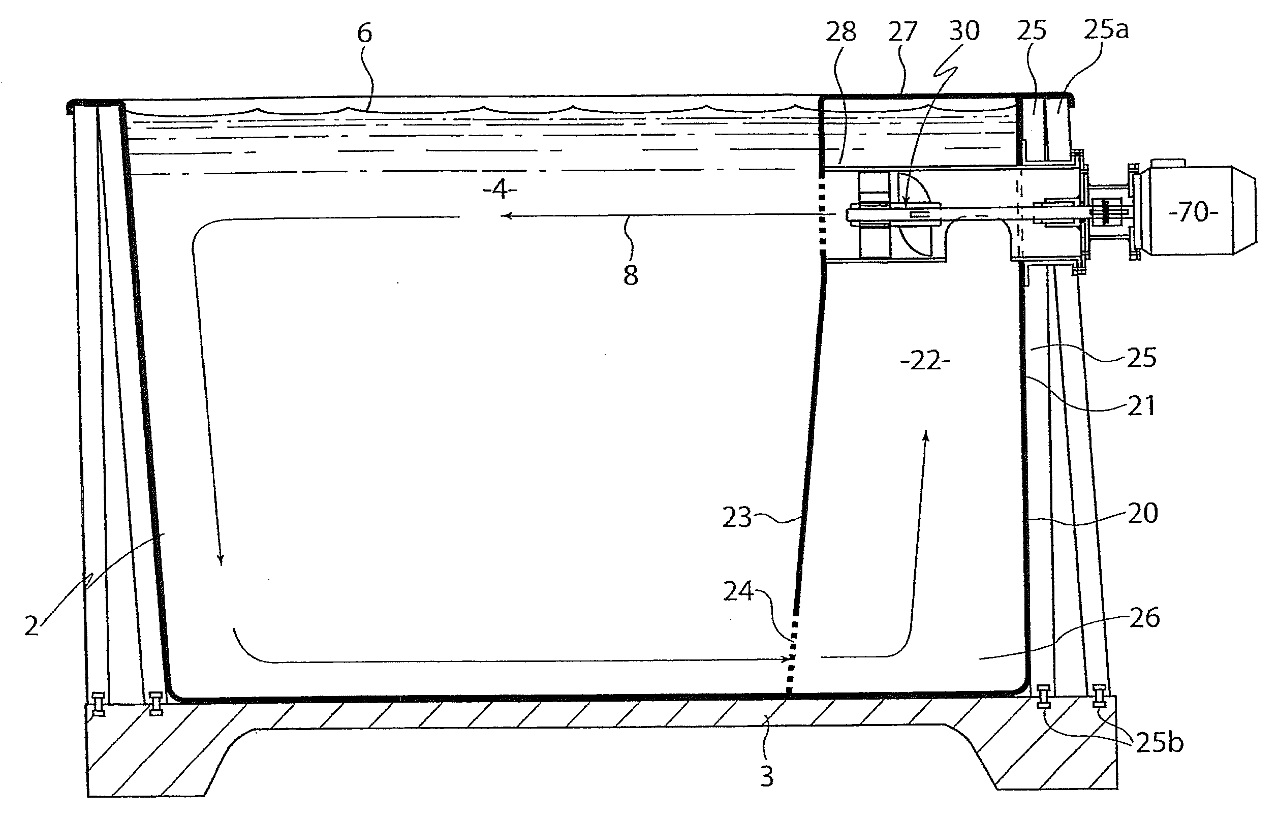
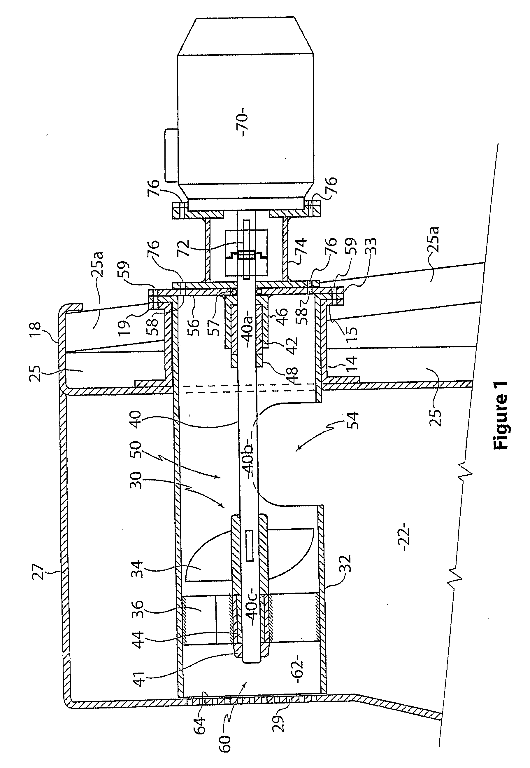
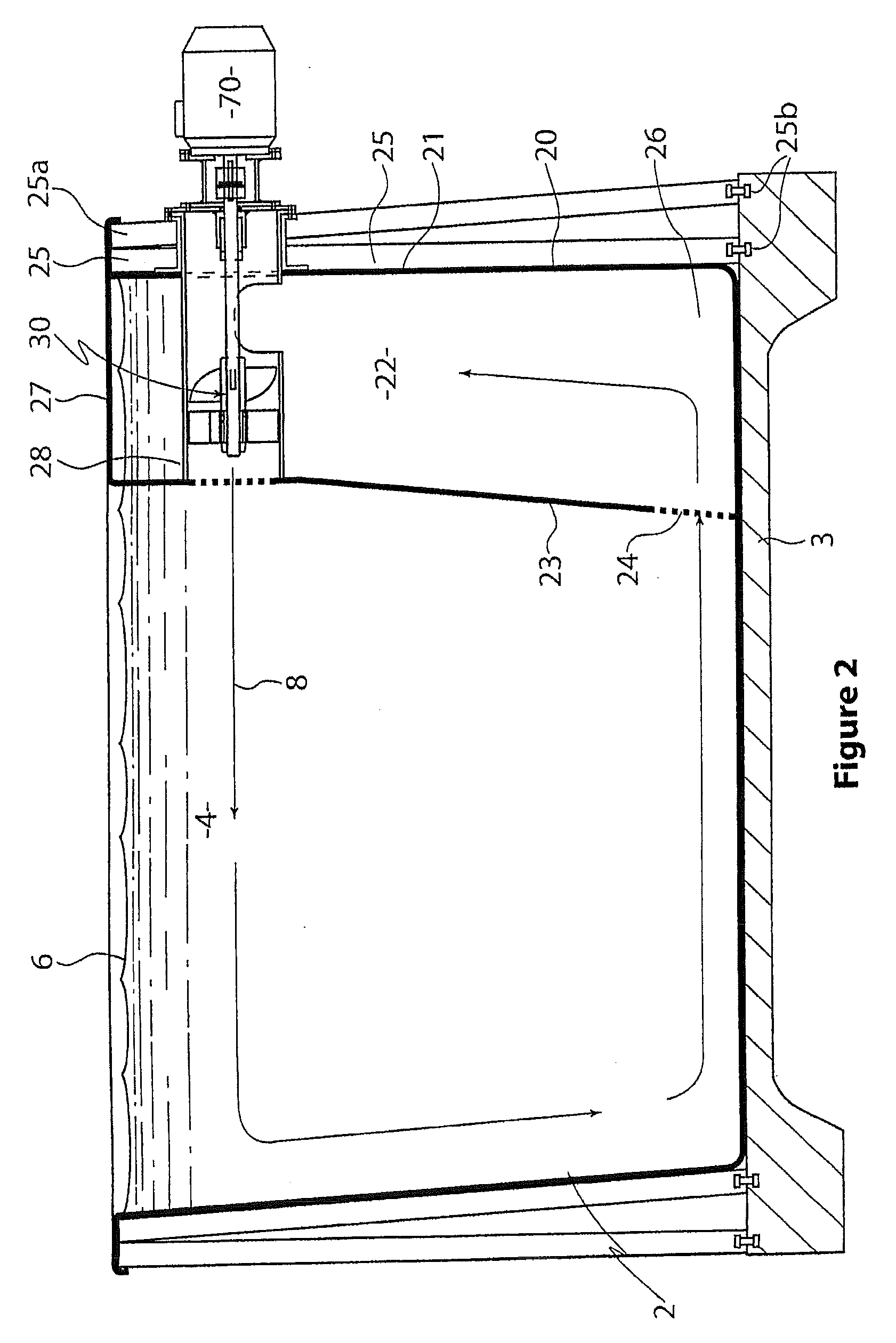
[0042]FIGS. 1 and 2 show cross-sectional views of apparatus for generating a current in a liquid containing vessel having an exercise zone.

[0043]The vessel 2 may be a swimming pool, spa bath or similar, containing water, chlorinated, salt or other treated liquid for swimming in, having an exercise or swimming zone 4 through which a current 8 flows. The terms ‘liquid’ and ‘water’ are hereinafter used in a generally interchangeable manner.

[0044]A swimmer (not shown) swimming in swimming zone 4 may swim against the current generated 8 to maintain a stationary position. Referring to FIG. 2, water is discharged from the pump 30 in a substantially horizontal direction from a point below the water surface level 6. A current 8 flows across the top or upper end of the vessel 2 as liquid is drawn back (generally counter-clockwise in the view of FIG. 2) through the axial pump 30 via an intake chamber 22 having an intake zone 24 at a lower end 26 of the intake chamber 22. The pump 30 is mounted...


PUM


Abstract

An apparatus for generating a current in a pool, the apparatus including:a) a shell including an upwardly extending intake chamber in fluid communication with the pool, the intake chamber having a liquid intake zone located in a lower end of the intake chamber;b) an axial pump having an upstream suction-side and a downstream discharge-side, the pump located at an upper end of the intake chamber, the pump having a guide means arranged to direct liquid to flow longitudinally in the discharge-side channel substantially without swirling, the guide means being located downstream of the pumping element; andc) drive means adapted to drive the drive shaft, wherein driving the drive shaft produces a discharge of liquid through the discharge-side outlet, to create a current in the pool for a swimmer to swim against.

Description

RELATED APPLICATION[0001]This application claims priority under 35 U.S.C. §119 from Australian Provisional Patent Application No. 2008904719, which was filed on Sep. 10, 2008, and the complete disclosure of which is hereby incorporated by reference.FIELD OF THE INVENTION[0002]This invention relates to apparatus for generating a current in a swimming pool or other vessel containing a liquid such as water.BACKGROUND TO THE INVENTION[0003]These have previously been proposed various types of apparatus for generating water currents in swimming pools whereby the water current acts as resistance to a swimmer so that swimming exercises can be carried out in a pool of quite short length. Hitherto, most types of water current generating apparatus for swimming pools have consisted of a water inlet and intake pipe mounted in a wall of the swimming pool, a separate outlet pipe and water outlet mounted in another location of the swimming pool and pump or jet means for receiving water from the inl...

Claims


Application Information

Patent Timeline
Patent Type & Authority Applications(United States)
IPC IPC(8): E04H4/12F04D27/00
CPCA63B69/125F04D29/548F04D3/00E04H4/0006
Inventor CLAREY, MICHAEL
Owner CLAREY MICHAEL
Learn More