Rotary shaver with improved support structure for shaving heads
Active Publication Date: 2010-03-11
KONINKLJIJKE PHILIPS NV
View PDF12 Cites 16 Cited by
Summary
Abstract
Description
Claims
Application Information
AI Technical Summary
This helps you quickly interpret patents by identifying the three key elements:
Problems solved by technology
Method used
Benefits of technology
[0004]It is an object of the invention to provide a shaving device of the kind mentioned in the opening paragrap
Problems solved by technology
Since in the coupled state the head structure is not supported in the area of its outer circumference, the area of the outer circumference cannot contribute in transferring the external load to the base structure.
Since in addition the coupling element is arranged in the central area of the head structure, the mechanical torque associated with the external load will lead to a relatively high force on the coupling element.
Therefore, when a
Method used
Image
Click on the blue label to locate the original text in one second.
Reading with bidirectional positioning of images and text.
Examples
Example
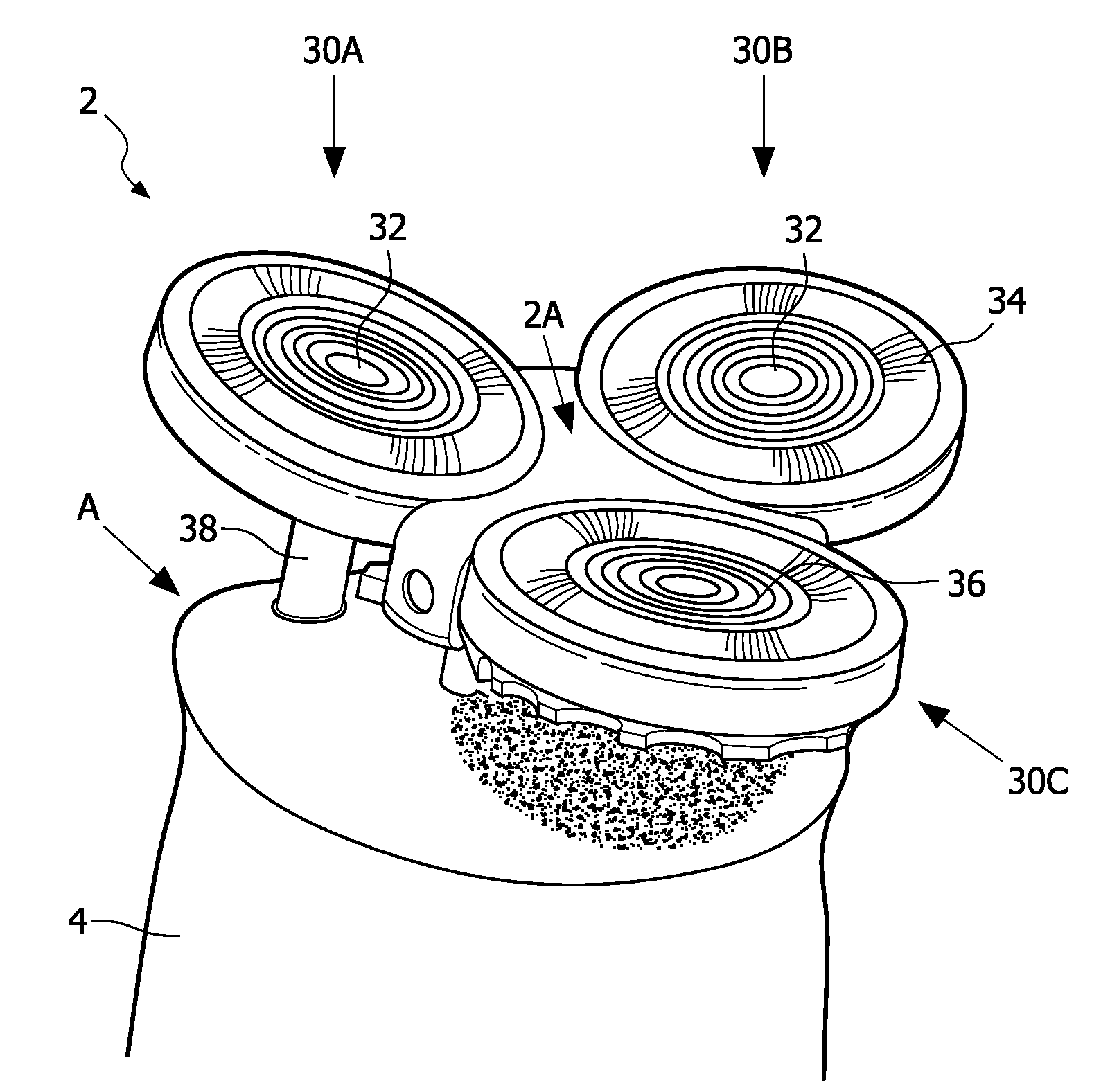
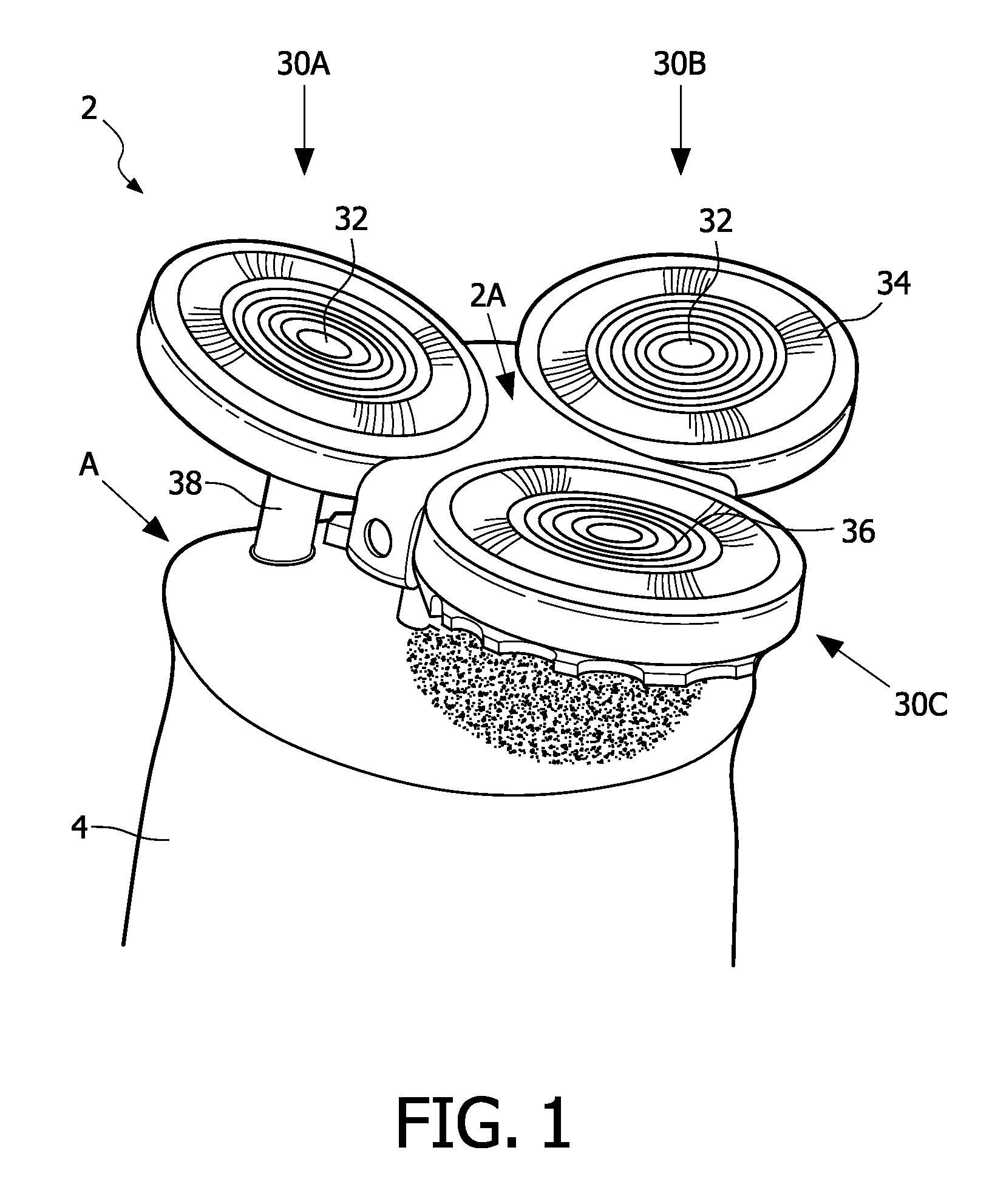
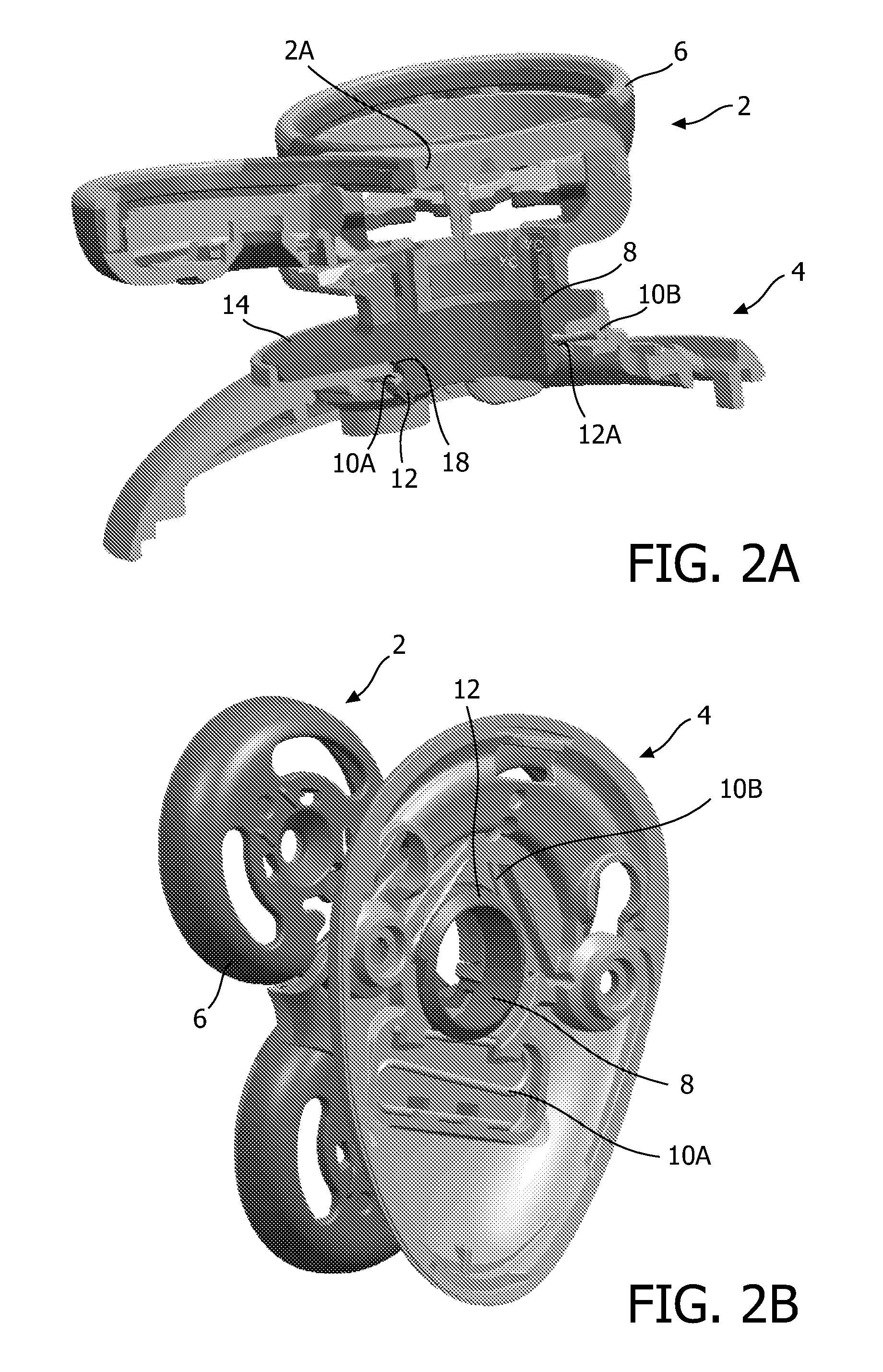
[0027]Referring to FIGS. 2A-2D, in a first embodiment according to the present invention, the head structure 2 is releasably connectable to the base structure 4. The base structure 4 as shown is to be mounted on a handle structure of a device, such as a shaving device as shown in FIG. 1. As used herein, the base structure may be an element to be mounted on a handle structure, as shown in FIGS. 2A-2D, or the term ‘base structure’ may refer to a handle structure as a whole, as shown in FIG. 1.
[0028]It is noted that a similar assembly of a head structure and a base structure may be applied in similar devices, such as a trimming device, tooth brush device, a grooming device, and the like. Further, the construction of the assembly may as well be advantageously employed for using a number of different head structures, such as a trimming head structure, a shaving head structure, a grooming head structure, a tooth brush head structure, and the like, in combination with a single base structu...
Example
[0034]In a second embodiment, as illustrated in FIGS. 3-5B, the outer diameter of the coupling element 8 is substantially equal to the inner diameter of the retaining recess.
[0035]Referring to FIG. 3, a head structure 2 comprises a coupling element 8 provided with a coupling recess 16 having a sloped surface 16A. The distal end 20 of the coupling element 8 is beveled.
[0036]As illustrated, the coupling element 8 is inserted in a retaining recess 18 of a base structure 4. A spring element 10 engages the sloped surface 16A, thereby clamping and retaining the coupling element 8 in the retaining recess 8. A collar 14 prevents that the coupling element 8 is further inserted into the retaining recess 18.
[0037]FIGS. 4A-4C illustrate an insertion of the coupling element 8 into the retaining recess 18. As the spring element 10 is to engage the sloped surface 16A of the coupling recess 16 in the coupling element 8, a distance between a first arm 10C and a second arm 10D of the spring element 1...
PUM
Abstract
A shaving device comprises a head structure (2) and a base structure (4). The head structure (2) is configured to retain and support at least one shaving head (30A, 30B, 30C). The head structure (2) is releasably retainable on the base structure (4). The base structure (4) is free of support elements in an area of an outer circumference of the head structure (2) such that the head structure (2), when coupled to the base structure (4), is not supported in the area of its outer circumference. The head structure (2), when coupled to the base structure (4), is substantially only retained on the base structure (4) by a retaining force provided by a retaining structure of the base structure (4). When an overloading force is exerted on the head structure (2), the force is transferred to a coupling element (8) arranged in a central area (2A) of the head structure (2) such that the coupling element (8) is released from the retaining structure of the base structure (4) in order to prevent damage to the head structure (2).
Description
FIELD OF THE INVENTION[0001]The present invention relates to a shaving device comprising a shaving head, and in particular to a shaving device comprising a base structure and a head structure, wherein the head structure comprises a head support structure configured to hold at least one shaving head.BACKGROUND OF THE INVENTION[0002]A shaving device of the above-mentioned kind is known e.g. from U.S. Pat. No. 2,253,737 and GB 965,791. Both documents disclose a shaving device comprising a base structure which operates as a handling structure and comprises an actuator for actuating the shaving heads. Furthermore, the shaving devices comprise a head structure comprising at least one shaving head. The head structure and the base structure are releasably coupled such that the head structure may be removed from the base structure, e.g. for cleaning.[0003]The above-mentioned known shaving devices are designed such that the head structure is configured for deliberate removal by a user. In cas...
Claims
Application Information
Patent Timeline
Application Date:The date an application was filed.
Publication Date:The date a patent or application was officially published.
First Publication Date:The earliest publication date of a patent with the same application number.
Issue Date:Publication date of the patent grant document.
PCT Entry Date:The Entry date of PCT National Phase.
Estimated Expiry Date:The statutory expiry date of a patent right according to the Patent Law, and it is the longest term of protection that the patent right can achieve without the termination of the patent right due to other reasons(Term extension factor has been taken into account ).
Invalid Date:Actual expiry date is based on effective date or publication date of legal transaction data of invalid patent.