Suction valve pulse width modulation control based on evaporator or condenser pressure

a pulse width modulation and valve technology, applied in the direction of process control, lighting and heating equipment, instruments, etc., can solve the problems of modulation valve, inability to control the operation of expansion valve, and system pressures across the refrigerant system can have undesirably large fluctuations, so as to reduce pressure fluctuation, increase the cycling rate of the valve, and the capacity provided by the refrigerant system can be varied.

Active Publication Date: 2010-03-11
CARRIER CORP
View PDF10 Cites 10 Cited by
  • Summary
  • Abstract
  • Description
  • Claims
  • Application Information

AI Technical Summary

Benefits of technology

[0007]In a disclosed embodiment of this invention, a pulse width modulation control is provided for selectively varying the amount of refrigerant flow passing from an evaporator downstream to the compressor. By controlling the amount of refrigerant flow passing through a suction pulse width modulation valve, the capacity provided by the refrigerant system can be varied. The control monitors signals indicative of at least one system pressure, and ensures that the pressure does not fluctuate outside of specified limits. The duty cycle of the suction pulse width modulation valve is selected to ensure that the pressure fluctuations stay within those limits. In a disclosed embodiment, the system pressure is monitored either at the condenser or the evaporator, or both. Should the pressure fluctuations approach the limits, then the suction pulse width modulation valve cycling rate is adjusted to stay within the specified limits. On the other hand, as long as the pressure fluctuations are within the limits, no adjustment to the valve cycling rate may be required. One of the most effective methods for reduction of pressure fluctuation would be to increase the cycling rate of the valve. However, other parameters, such as, for example, the opening and closing time of the valve can be varied to achieve the desired result.

Problems solved by technology

One challenge raised by the prior art use of pulse width modulation controls is that while this technique does provide good control over capacity, the system pressures across the refrigerant system can have undesirably large fluctuations between the on / off positions of the suction pulse width modulation valve.
Such pressure fluctuations are undesirable and may make it difficult to control the operation of the expansion valve, it may become harder to maintain a constant temperature within the environment to be cooled, and the overall system operation may become less efficient.
On the other hand, if the valve is cycled too frequently to minimize the pressure fluctuations, there are additional losses associated with a system transition from the valve being open to the valve being in a closed position.
Further, the chance of valve failure increases due to the extensive cycling.
However, this disclosed control does not specifically seek to minimize fluctuations, does not control a suction pulse width modulation valve, and also does not monitor conditions on the discharge (high pressure) side of the system.

Method used


Image

  • Suction valve pulse width modulation control based on evaporator or condenser pressure
  • Suction valve pulse width modulation control based on evaporator or condenser pressure

Examples


Embodiment Construction

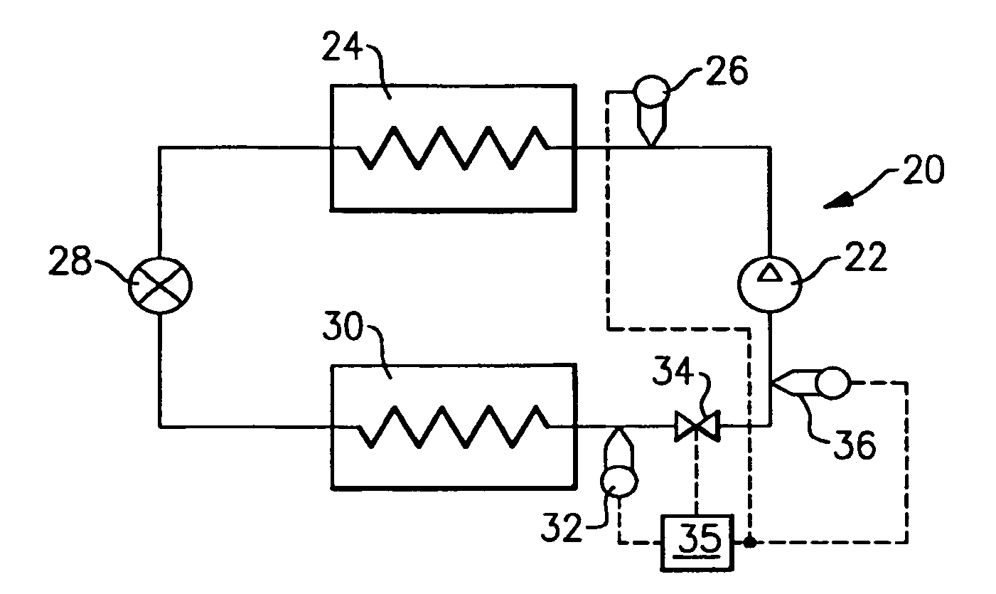
[0012]A refrigerant system 20 is illustrated in FIG. 1 having a compressor 22 compressing a refrigerant and delivering it downstream to a condenser 24. A pressure sensor 26 senses the pressure near or at the condenser 24. The refrigerant passes downstream to an expansion valve 28, and then to an evaporator 30. A pressure sensor 32 senses the pressure of the refrigerant near or at the evaporator 30. A suction pulse width modulation valve 34 is positioned downstream of the evaporator 30. A control 35 controls the opening of the suction pulse width modulation valve. A pressure sensor 36 senses the pressure of the suction line leading from the suction pulse width modulation valve 34 back to the compressor 22.

[0013]The pressure associated with the condenser 24 (sensed by the sensor 26) and with the evaporator 30 (sensed by the sensor 32) are both transmitted to the control 35. The control 35 is programmed to achieve benefits as set forth below.

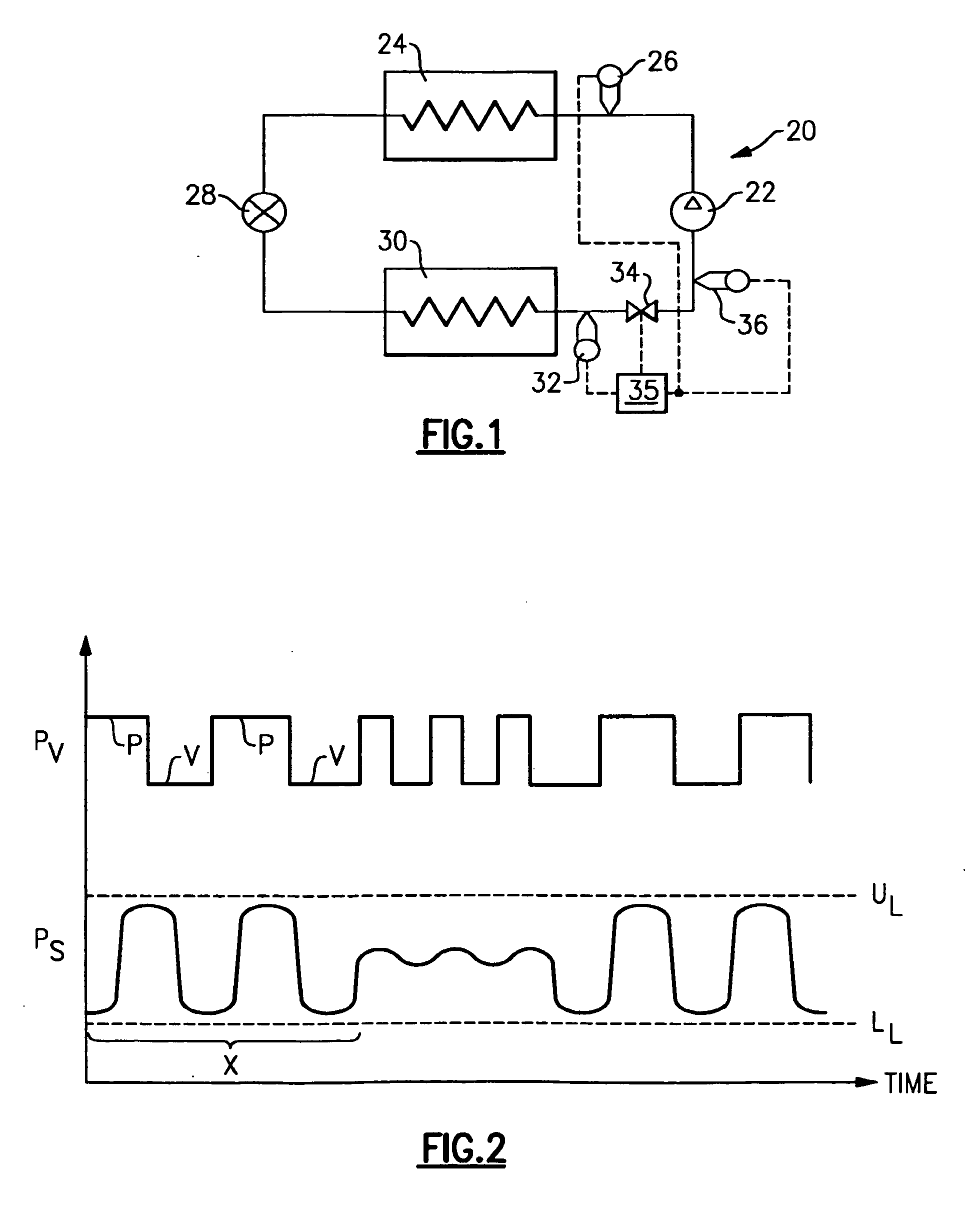
[0014]As shown in FIG. 2, the opening of the...


PUM


Abstract

A refrigerant system is provided with a suction pulse width modulation valve, and a pulse width modulation control for controlling this valve. System pressures, such as the pressure on the evaporator and the condenser are monitored. The measured system pressures are maintained within a band of acceptable lower and upper limits. As the pulse width modulation control cycles the valve, the refrigerant pressures in the evaporator and the condenser tend to fluctuate. The control ensures those fluctuations are within the limits by controlling the duty cycle of the valve.

Description

BACKGROUND OF THE INVENTION[0001]This application relates to a pulse width modulation control for a suction pulse width modulation valve that allows for continuous or precise stepwise capacity to be provided by a refrigerant system, and wherein system pressures are monitored to determine an optimum duty cycle for the pulse width modulation.[0002]Refrigerant systems are utilized in many applications such as to condition an environment. Air conditioners and heat pumps are used to cool and / or heat the air entering an environment. The cooling or heating load on the environment may change with ambient conditions, and as the temperature and / or humidity levels demanded by an occupant of the environment vary. Obviously, the refrigerant system operation and control have to adequately reflect these changes to maintain stable temperature and humidity conditions within the environment.[0003]One method that is known in the prior art to assist in the adjustment of capacity from a refrigerant syst...

Claims


Application Information

Patent Timeline
Patent Type & Authority Applications(United States)
IPC IPC(8): F25B1/00G05D7/00
CPCF25B41/043F25B49/02F25B2700/197F25B2700/1933F25B2700/195F25B2600/2521F25B41/22
Inventor LIFSON, ALEXANDERTARAS, MICHAEL F.
Owner CARRIER CORP
Why Eureka
Try Eureka