
Sheet feed device and image recording apparatus having such sheet feed device

a technology of image recording apparatus and feed device, which is applied in the direction of pile separation, instruments, transportation and packaging, etc., can solve the problems of burdening the user, not being able to feed sheets in the first sheet cassette, etc., and achieves the effect of convenient reloading

Inactive Publication Date: 2010-03-11
BROTHER KOGYO KK
View PDF21 Cites 11 Cited by
  • Summary
  • Abstract
  • Description
  • Claims
  • Application Information

AI Technical Summary

Benefits of technology

The present invention is a sheet feed device that can selectively feed different types of sheets, such as sheets having different sizes, from two sheet cassettes while reducing user interaction with the cassettes. The device includes a sheet feeder and a sheet separator for separating sheets. The second sheet cassette can move above the accommodating portion and selectively feed the first and second plurality of sheets. The sheet feed device can be incorporated into an image recording apparatus, allowing for easy reloading of sheets. The technical effects of the invention are improved efficiency and flexibility in sheet feeding for different applications.

Problems solved by technology

Consequently, in order to record an image on a plurality of postcards, it is necessary for the user to place one postcard at a time on the partition plate, and to move the partition plate back and forth, which is burdensome to the user.
In other words, it is not possible to feed sheets in the first sheet cassette that are different in size from those feed sheets in the second sheet cassette, in a state where the second sheet cassette is set in the first sheet cassette.
Consequently, the user must attach and detach the second sheet cassette each time that the sheets to be used are switched, which is burdensome to the user.

Method used


Image

  • Sheet feed device and image recording apparatus having such sheet feed device
  • Sheet feed device and image recording apparatus having such sheet feed device
  • Sheet feed device and image recording apparatus having such sheet feed device

Examples


first embodiment

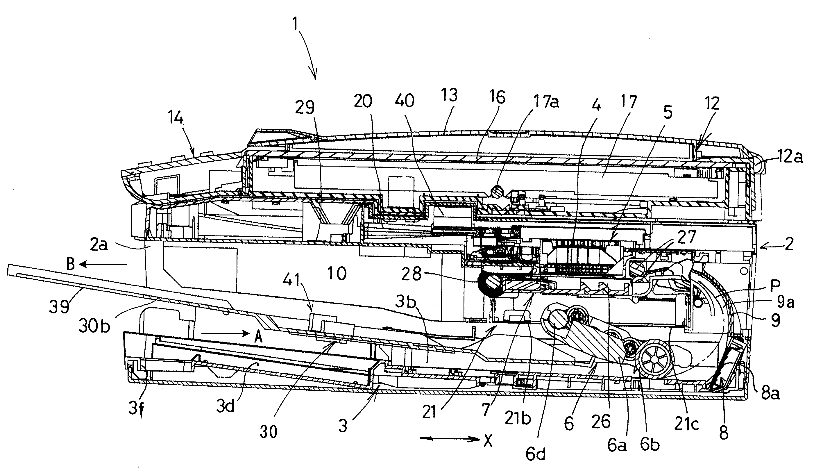
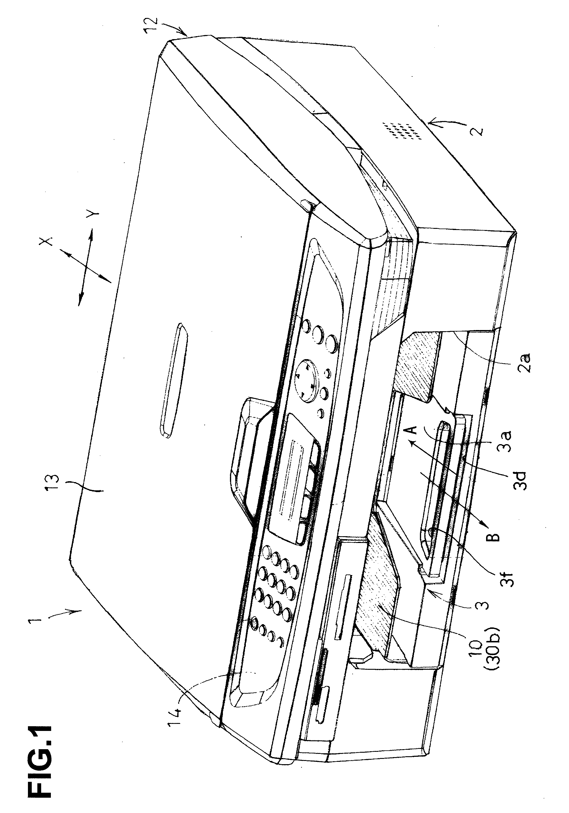
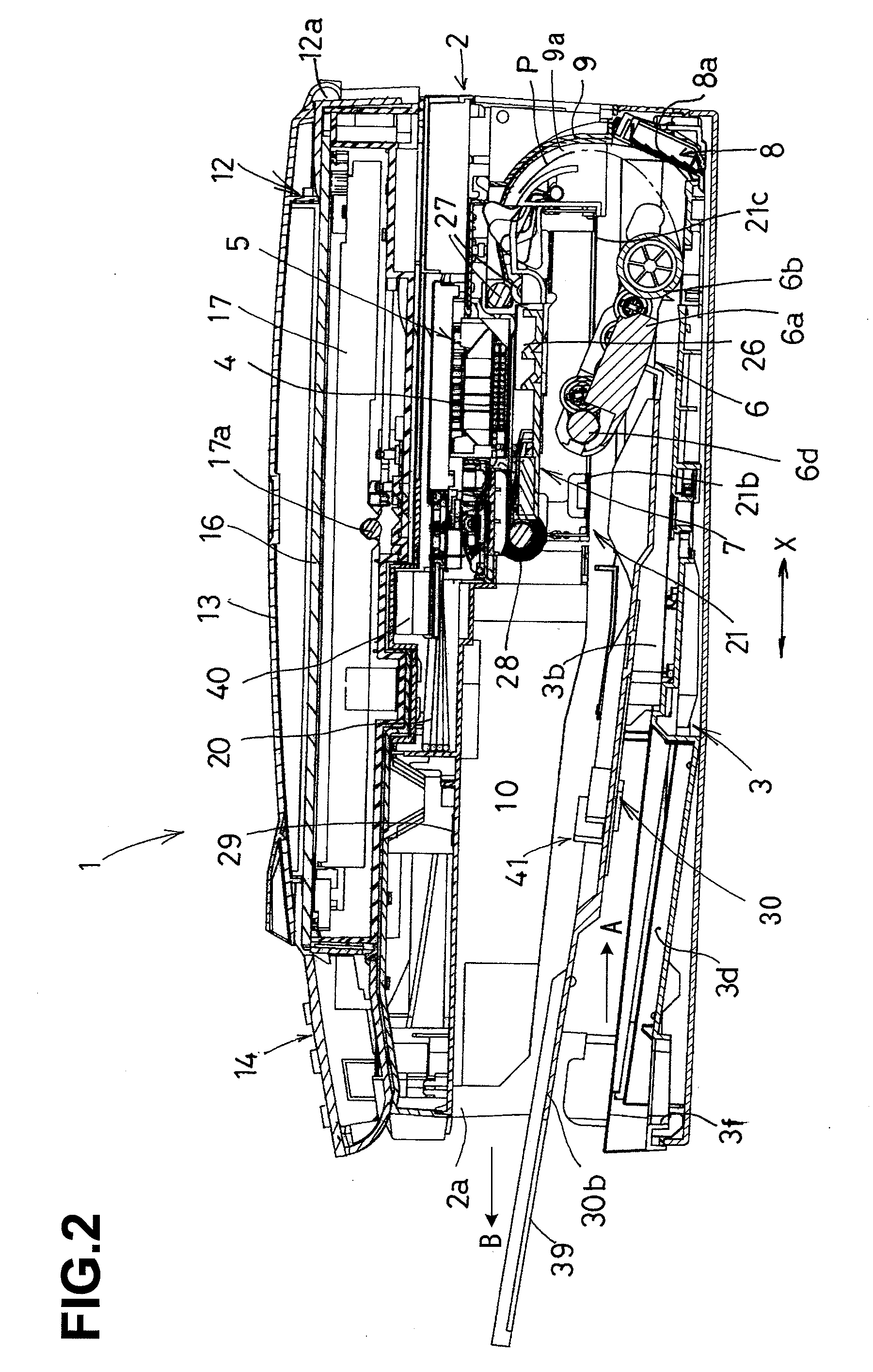
[0073]The structure of a sheet feed device 100 according to the present invention will now be described. In this embodiment, sheet feed device 100 comprises a first sheet cassette 3 and a second sheet cassette 30. First sheet cassette 3 has an accommodating portion 3b configured to accommodate a stack of sheets P, and sheets P in accommodating portion 3b may be fed in a sheet feed direction (indicated by arrow A) toward recording unit 7 one by one by a sheet feeder 6. Second sheet cassette 30 may be disposed above accommodating portion 3b and may be movable back and forth with respect to sheet feeder 6. Second sheet cassette 30 may be configured to accommodate a stack of sheets P1 that are different in size from the sheets P accommodated in first sheet cassette 3, e.g., sheets P1 may be smaller-sized sheets, such as postcards and L-sized photograph sheets. The sheets P1 in second sheet cassette 30 may be fed in the same direction as the feed direction of the sheets P. When second sh...

second embodiment

[0107]FIGS. 21-24 show a sheet feed device 101 according to the present invention. In this embodiment, a sheet feed roller 6b of a sheet feeder 306 is moved up and down corresponding to the back and forth movements of a first sheet cassette 303 and a second sheet cassette 330. A cam follower 43 shaped like a flat plate may project integrally, from a sheet feed arm 6a (drive shaft 6d is omitted from FIGS. 21-23) and extends towards and over an auxiliary cam 44 and a main cam 55. Auxiliary cam 44 may be formed to have a varying height on an upper surface of one of side plates 30c of second sheet cassettes 30, and main cam 55 may be formed to have a varying height on an upper surface of one of side plate 3c of first sheet cassette 303. An end 43a of cam follower 43, which contacts main cam 55, has a length L1 in the sheet-feed direction, while cam follower 43, which contacts auxiliary cam 44, has a length L2. L1 may be smaller than L2, as shown in FIG. 22.

[0108]Auxiliary cam 44 may be ...

third embodiment

[0116]FIGS. 25-28 show a sheet feed device 102 according to the present invention. In this embodiment, a first sheet feeder 306 for a first sheet cassette 403 and a second sheet feeder 60 for a second sheet cassette 430 may be disposed side by side, and first sheet feeder 306 and second sheet feeder 60 may be configured to be raised or lowered selectively. When sheets P in first sheet cassette 403 are fed, a sheet feed roller 6b of first sheet feeder 306 contacts the uppermost one of the sheets P in an accommodating portion 3b of first sheet cassette 403, and a sheet feed roller 60b of second sheet feeder 60 is held at a raised position. On the other hand, when sheets P1 in the second sheet cassette 430 are fed, the second sheet feed roller 60b of the second sheet feeder 60 contacts the uppermost one of the sheets P1 on a holding portion 30a of second sheet cassette 430, and sheet feed roller 6b of first sheet feeder 306 is kept at a raised position.

[0117]To be more specific, a main...


PUM

PropertyMeasurementUnit
heightaaaaaaaaaa
shapeaaaaaaaaaa
sizeaaaaaaaaaa

Abstract

A sheet feed device includes a first sheet cassette having an accommodating portion accommodating a first plurality of sheets and a second sheet cassette, disposed on the first sheet cassette, accommodating a second plurality of sheets. The sheet feed device also includes a sheet feeder configured to selectively feed the first plurality of sheets and the second plurality of sheets toward a sheet feed path, and a sheet separator configured to separate, one by one, the sheets fed by the sheet feeder. Specifically, the second sheet cassette is configured to move above the accommodating portion and with respect to the sheet feeder between a sheet feed position in which the sheet feeder contacts sheets accommodated in the second sheet feed cassette to a non-sheet feed position in which the second sheet feed cassette prevents the sheet feeder from contacting sheets accommodated in the second sheet feed cassette.

Description

CROSS REFERENCE TO RELATED APPLICATIONS[0001]The present application claims priority from Japanese Patent Application Nos. 2005-99607, 2005-99608, 2005-99609, and 2005-99610, each of which were filed on Mar. 30, 2005, the disclosures of which are incorporated herein by reference in their entirety.BACKGROUND OF THE INVENTION[0002]1. Field of the Invention[0003]The present invention relates generally to a sheet feed device that includes a first sheet cassette and a second sheet cassette disposed on the first sheet cassette, and selectively feeds sheets (recording media) that are positioned in the first sheet cassette or sheets that are positioned in the second sheet cassette and are different than, e.g., smaller than, the sheets in the first sheet cassette. The present invention also relates to an image recording apparatus having such a sheet feed device.[0004]2. Description of Related Art[0005]A sheet feed device used in a known image recording apparatus, such as a printer and / or a f...

Claims


Application Information

Patent Timeline
Patent Type & Authority Applications(United States)
IPC IPC(8): B65H5/26B65H5/00B65H1/08
CPCB41J11/485B41J13/103B65H1/04B65H1/22B65H1/28B65H2701/1131B65H3/44B65H2301/422548B65H2405/332B65H2601/322B65H3/0669B65H1/266B65H3/66B65H2405/32G06K15/102H04N1/0057H04N1/00602H04N1/00604H04N1/00623H04N2201/0094
Inventor SHIOHARA, YUKIOASADA, TETSUOKOGA, YUJI
Owner BROTHER KOGYO KK
Learn More