Seal assembly

a technology of assembly and bolting, which is applied in the direction of engine seals, mechanical devices, engine components, etc., can solve the problems of additional components of the scraper, the scraper ring and the bolted endcap have the disadvantage, and achieve the effects of less weight, small space, and lower hardware cos

Active Publication Date: 2010-03-11
TRELLEBORG SEALING SOLUTIONS GERMANY
View PDF34 Cites 48 Cited by
  • Summary
  • Abstract
  • Description
  • Claims
  • Application Information

AI Technical Summary

Benefits of technology

[0012]An advantage of the present invention is that it provides a seal assembly which is a combination seal and wiper.
[0013]Another advantage of the present invention is that it combines two or more products to form the seal assembly. That is, the seal assembly can include: a) a seal and a wiper; b) a seal and a wiper, as well as a retention device; c) a seal and a wiper, as well as a bearing; and d) a seal and a wiper, as well as a retention device and a bearing. Each of the variations includes either a central structural element or at least one can (the central structural element and the at least one can being referred to generally as a structural element).
[0014]Another advantage of the present invention is that it provides, to an end-user, a smaller space, less weight, lower cost hardware, a reduction in the number of parts, easier assembly, less installation time, a lower cost seal, damage tolerance, less system cost, and more bearing space.
[0015]Yet another advantage of the present invention is that the seal assembly, which is a combination seal and wiper, can be used in an environment up to 3,000 psi, the seal assembly being either a unitized seal assembly or a one-piece seal assembly. The seal assembly of the present invention thus includes a seal and a wiper (which is thus a combination seal and wipe

Problems solved by technology

A disadvantage of seal system 31 is that it includes a number of components 33, 35, 37 which are separate from one another and requires thr

Method used


Image

  • Seal assembly
  • Seal assembly
  • Seal assembly

Examples


Embodiment Construction

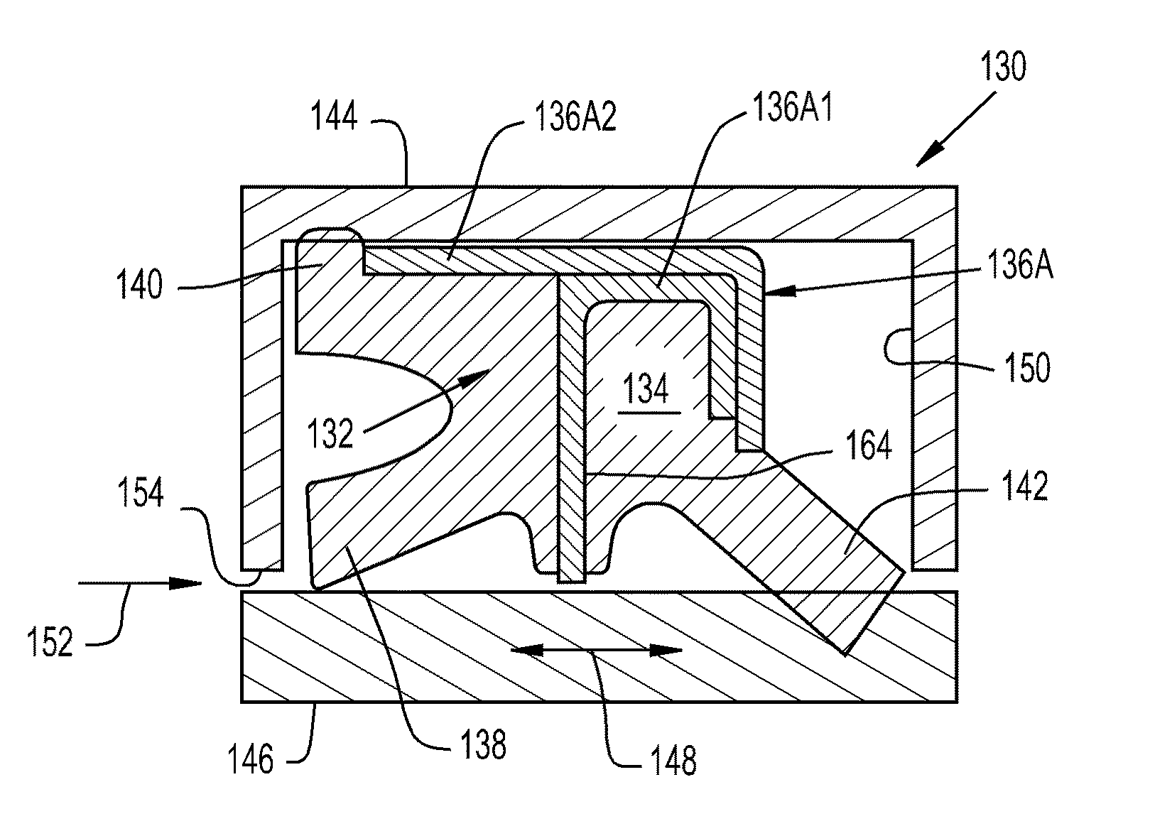
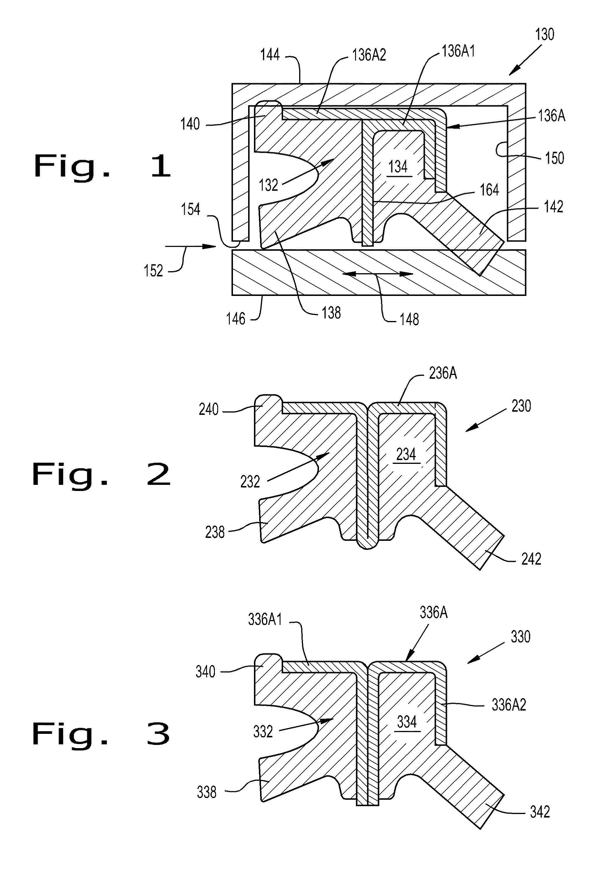
[0051]Referring now to the drawings, and more particularly to FIG. 1, there is shown a seal assembly 130 which generally includes a seal element 132, a wiper element 134, and a structural element 136A attached to seal element 132 and wiper element 134 and thereby providing a combination seal and wiper 130. Seal element 132 includes at least one seal lip 138; more specifically, FIG. 1 shows that seal element 132 includes an inside diameter seal lip 138 and an outside diameter seal lip 140. Wiper element 134 includes a wiper lip 142. Seal assembly 130 is configured for functioning under pressure 152 in an amount greater than 500 pounds per square inch (psi). Seal assembly 130 can function under pressure 152 in an amount up to 3,000 psi.

[0052]The present invention, as indicated above, can be used in reciprocating, linear applications, but is not necessarily limited to these applications (it could be used in rotational applications as well). The seal assembly of the present invention ca...


PUM


Abstract

A seal assembly, includes a seal element including at least one seal lip, a wiper element including a wiper lip, and a structural element attached to the seal element and the wiper element, the seal assembly being configured for functioning under pressure in an amount greater than 500 pounds per square inch.

Description

CROSS REFERENCE TO RELATED APPLICATIONS[0001]This is a non-provisional application based upon U.S. provisional patent application Ser. No. 61 / 095,444, entitled “SEAL ASSEMBLY”, filed Sep. 9, 2008, which is incorporated herein by reference.BACKGROUND OF THE INVENTION[0002]1. Field of the Invention[0003]The present invention relates to seal assemblies, and, more particularly, to high pressure seal assemblies.[0004]2. Description of the Related Art[0005]Seals in the form of seal rings often provide sealing function in linear or rotational applications. In linear applications, the seal can be seated in a housing groove and seal against a reciprocating rod which is moving back-and-forth in a linear manner. In rotational applications, the seal can be seated in a housing groove and seal against a rotating rod. In either case, system pressure can be applied, for example, to one side of the seal. If the seal is not properly designed to handle a certain amount of upstream pressure, the seal c...

Claims


Application Information

Patent Timeline
IPC IPC(8): F16J15/32
CPCF16J15/3236F16J15/56F16J15/3268
Inventor CASTLEMAN, LARRYSITKO, MARK
Owner TRELLEBORG SEALING SOLUTIONS GERMANY
Why Eureka
Try Eureka