Electromagnetic relay

a technology of electromagnetic relays and relays, applied in electromagnetic relay details, contact mechanisms, electrical apparatus, etc., can solve the problems of arcs that cannot be reliably broken, arcs that cannot be reliably extended, and arcs that are difficult to reliably break, etc., to achieve the effect of reliably breaking arcs

Active Publication Date: 2010-03-11
ANDEN CORP
View PDF8 Cites 25 Cited by
  • Summary
  • Abstract
  • Description
  • Claims
  • Application Information

AI Technical Summary

Problems solved by technology

However, the arc sometimes cannot be extended sufficiently, and thereby the arc cannot be reliably broken simply by disposing the magnet near the moving contact and the fixed contact as in the conventional electromagnetic relay.
In an electromagnetic relay for high voltage (for example, a relay used for a hybrid electric vehicle with voltage of 400V), in particular, it is difficult to break the arc reliably because arc length becomes long.

Method used


Image

  • Electromagnetic relay
  • Electromagnetic relay
  • Electromagnetic relay

Examples


first embodiment

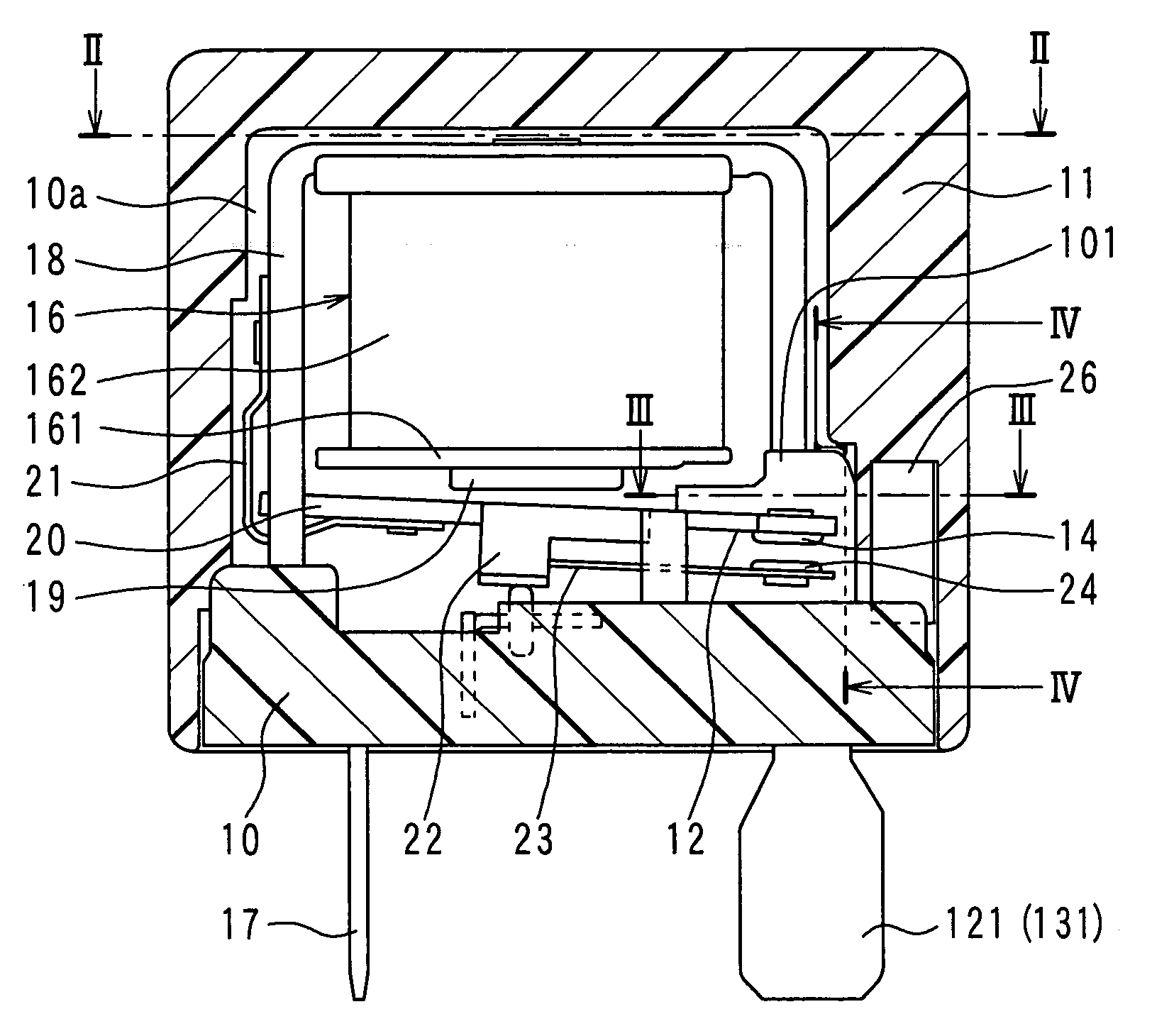
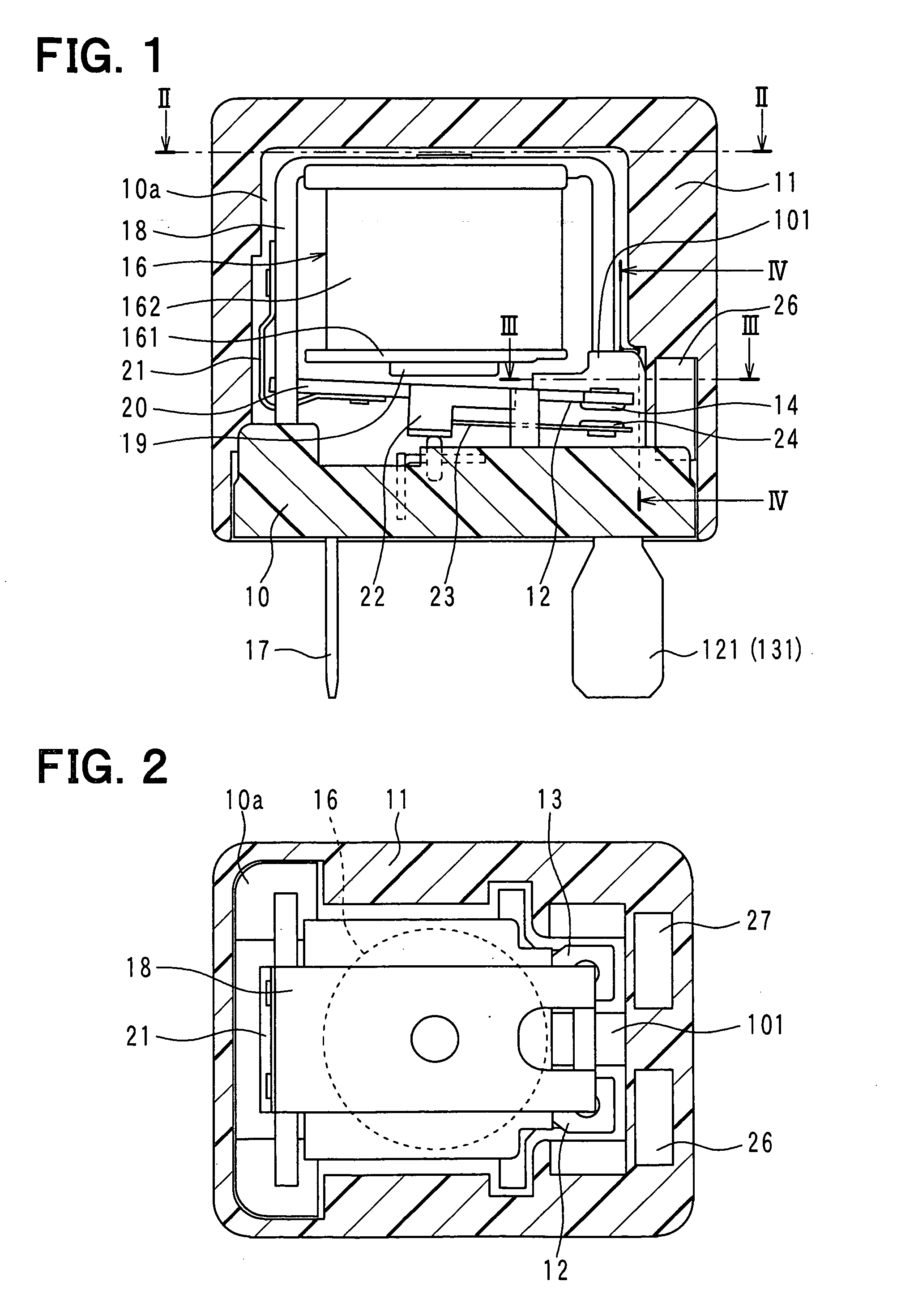
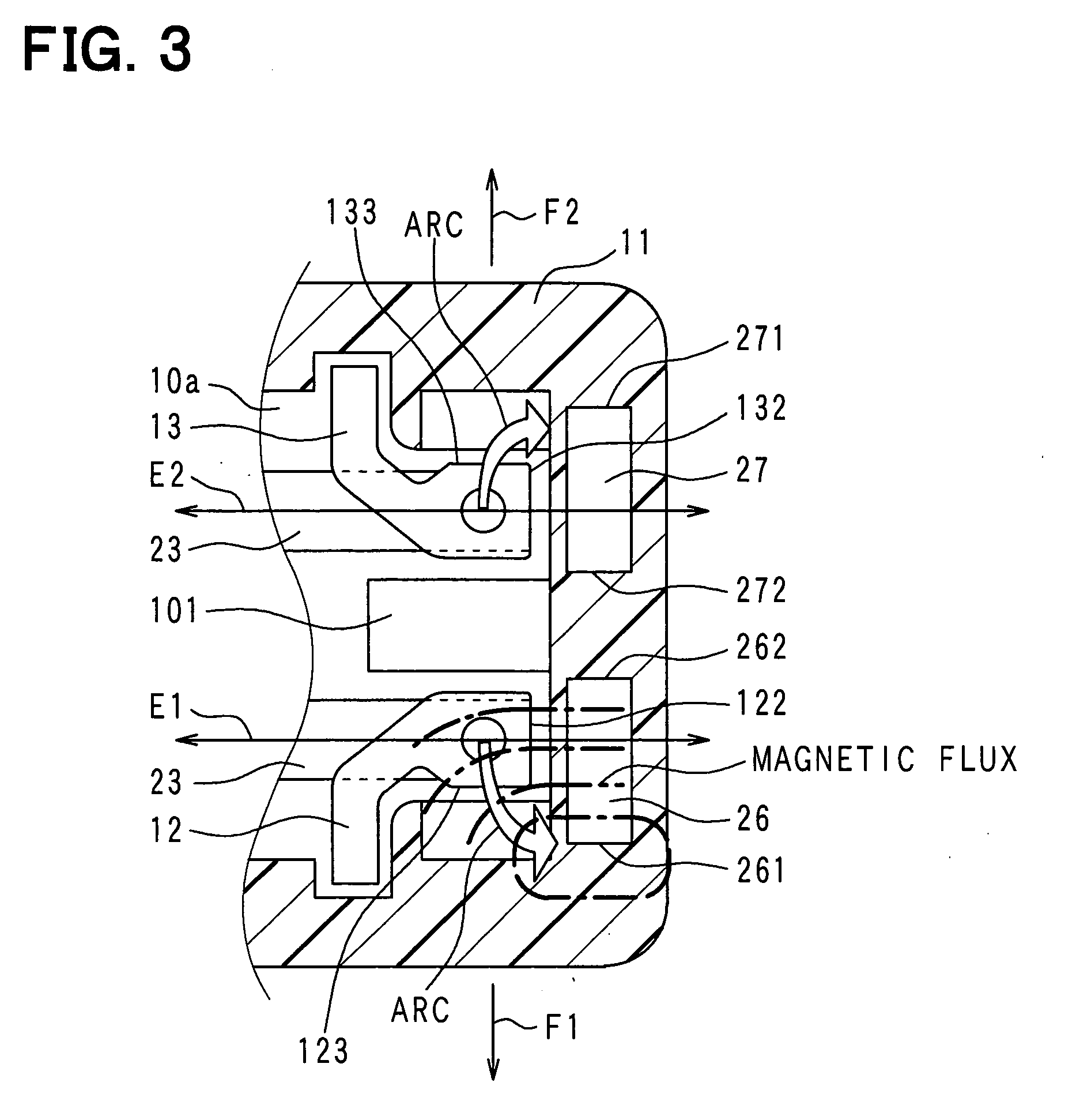
[0022]A first embodiment of the invention is described below with reference to FIG. 1 to FIG. 4.

[0023]An electromagnetic relay of the first embodiment includes a plate-like base 10 made of resin and a rectangular parallelepiped case 11 made of resin and formed in a cylindrical shape having a bottom portion, with the case 11 fitted to the base 10. A space (hereinafter referred to as an internal space) 10a is defined inside the relay by the base 10 and the case 11.

[0024]Two fixed contact holding members 12, 13 made of conductive metal are fixed to the base 10. The two fixed contact holding members 12, 13 penetrate through the base 10, and their one end side is located in the internal space 10a, whereas the other end side is located in an exterior space.

[0025]Fixed contacts 14, 15 made of conductive metal are calked and fixed respectively on end portions of the two fixed contact holding members 12,13 on the internal space 10a side. The two fixed contacts 14, 15 are positioned and held ...

second embodiment

[0060]A second embodiment of the invention is described below with reference to FIG. 5 to FIG. 9C. An electromagnetic relay according to the second embodiment includes a plate-like base 310 made of resin and a rectangular parallelepiped case 311 made of resin and formed in a cylindrical shape having a bottom portion. The base 310 is fitted in the case 311 so as to close an opening of the case 311, and a space (hereinafter referred to as an internal space) 310a is defined inside the relay by the base 310 and the case 311.

[0061]Two fixed contact holding members 312, 313 made of conductive metal are fixed to the base 310. The two fixed contact holding members 312, 313 penetrate through the base 310, and their one end side is located in the internal space 310a, whereas the other end side is located in an exterior space. In addition, their intermediate portions are located in through holes of the base 310.

[0062]Fixed contacts 314, 315 made of conductive metal are calked and fixed respect...


PUM


Abstract

An electromagnetic relay includes a case, a base, a magnet coil, a movable member driven by electromagnetic force of the coil, a moving contact, a fixed contact engaged with or disengaged from the moving contact, a fixed contact holding member fixed to the base with the holding member passing therethrough and having a load circuit terminal, and a magnet applying Lorentz force to arc generated between the fixed contact and the moving contact. The case includes a guide part on its region with which arc extended in a Lorentz force application direction collides. The guide part guides arc after the collision to extend arc in a different direction from the application direction. The case includes a case partition wall between the guide part and the base. The holding member has a guide part opposing portion opposed to the guide part. The opposing portion is covered with the case partition wall.

Description

CROSS REFERENCE TO RELATED APPLICATION[0001]This application is based on and incorporates herein by reference Japanese Patent Application No. 2008-228005 filed on Sep. 5, 2008, and Japanese Patent Application No. 2009-021295 filed on Feb. 2, 2009.BACKGROUND OF THE INVENTION[0002]1. Field of the Invention[0003]The present invention relates to an electromagnetic relay which opens and closes an electric circuit.[0004]2. Description of Related Art[0005]According to a conventional electromagnetic relay described in Japanese Unexamined Patent Application Publication No. 2006-351240, a fixed contact is positioned and held at a predetermined position by a fixed contact holding member, and a movable member, on which a moving contact is attached, is driven by electromagnetic force of a magnet coil, so that the moving contact is engaged with and disengaged from the fixed contact. Accordingly, the conventional relay opens and closes an electric circuit. Furthermore, a magnet is disposed near th...

Claims


Application Information

Patent Timeline
Patent Type & Authority Applications(United States)
IPC IPC(8): H01H50/60H01H50/04
CPCH01H50/24H01H9/443
Inventor NAGURA, HIROSHIITO, TAKASHITAKEYAMA, MASAKI
Owner ANDEN CORP
Why Eureka
Try Eureka