Illumination device and liquid crystal display device

Active Publication Date: 2010-03-11
SHARP KK
View PDF24 Cites 31 Cited by
  • Summary
  • Abstract
  • Description
  • Claims
  • Application Information

AI Technical Summary

Benefits of technology

[0040]The above arrangement causes the light amount adjusting section to cover the boundary between any adjacent two light guide plates. This allows light emitted from the end surface opposite from of the light source to be surely emitted onto the light amount adjusting section. In other words, no light emitted from the end surface leaks out directly to the outside without passing the light amount adjusting section. This surely reduces the amount of light causing bright lines, and thereby further improves luminance uniformity.
[0041]The illumination device of the present invention may be arranged such that the light amount adjusting section is made of a semi-transmissive

Problems solved by technology

However, in the illumination device configured by the combination of the light guide plates and the light sources as described above, aligning the plurality of light guide plates planerly pose

Method used


Image

  • Illumination device and liquid crystal display device
  • Illumination device and liquid crystal display device
  • Illumination device and liquid crystal display device

Examples


embodiment 1

[0067]A first embodiment of the present invention is described below with reference to FIGS. 1 through 7. Note that the present invention is not limited to this.

[0068]The present embodiment describes an illumination device used as a backlight of a liquid crystal display device.

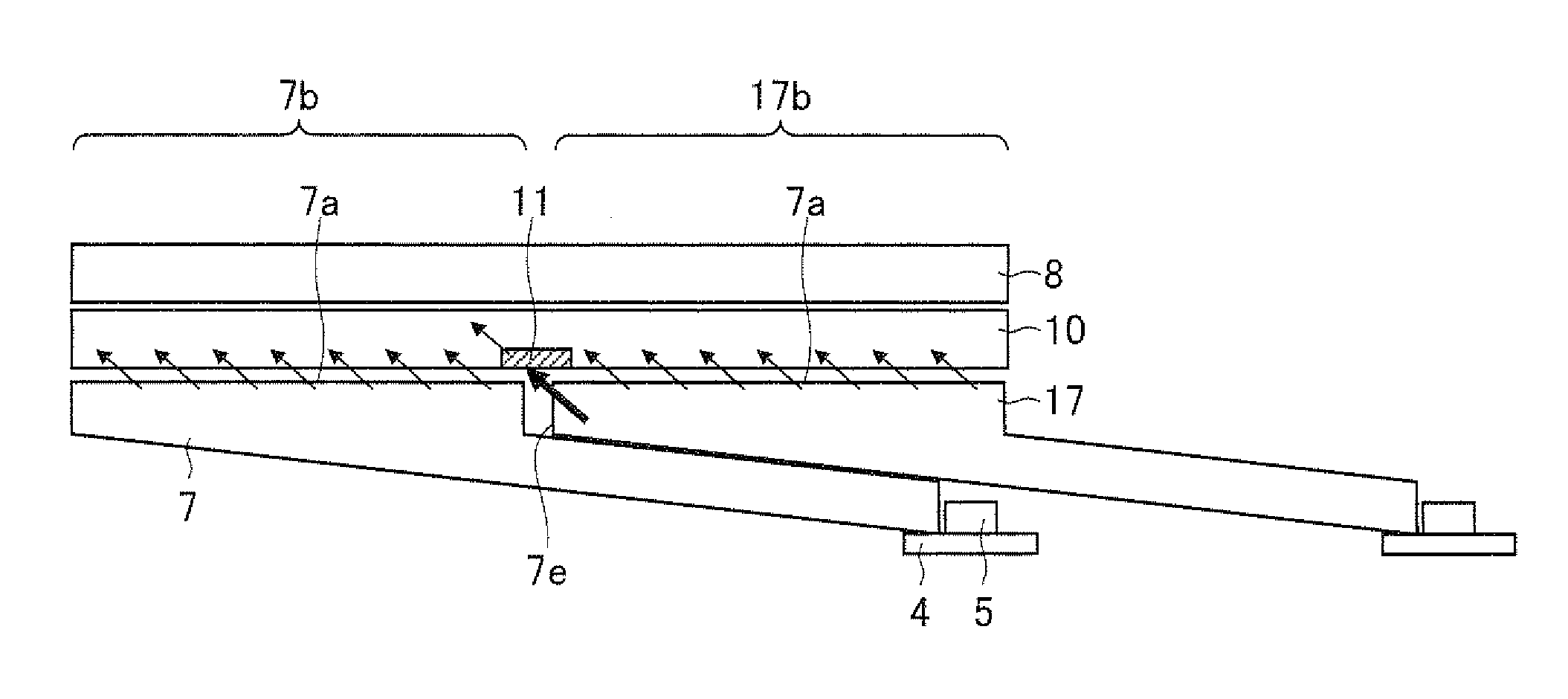
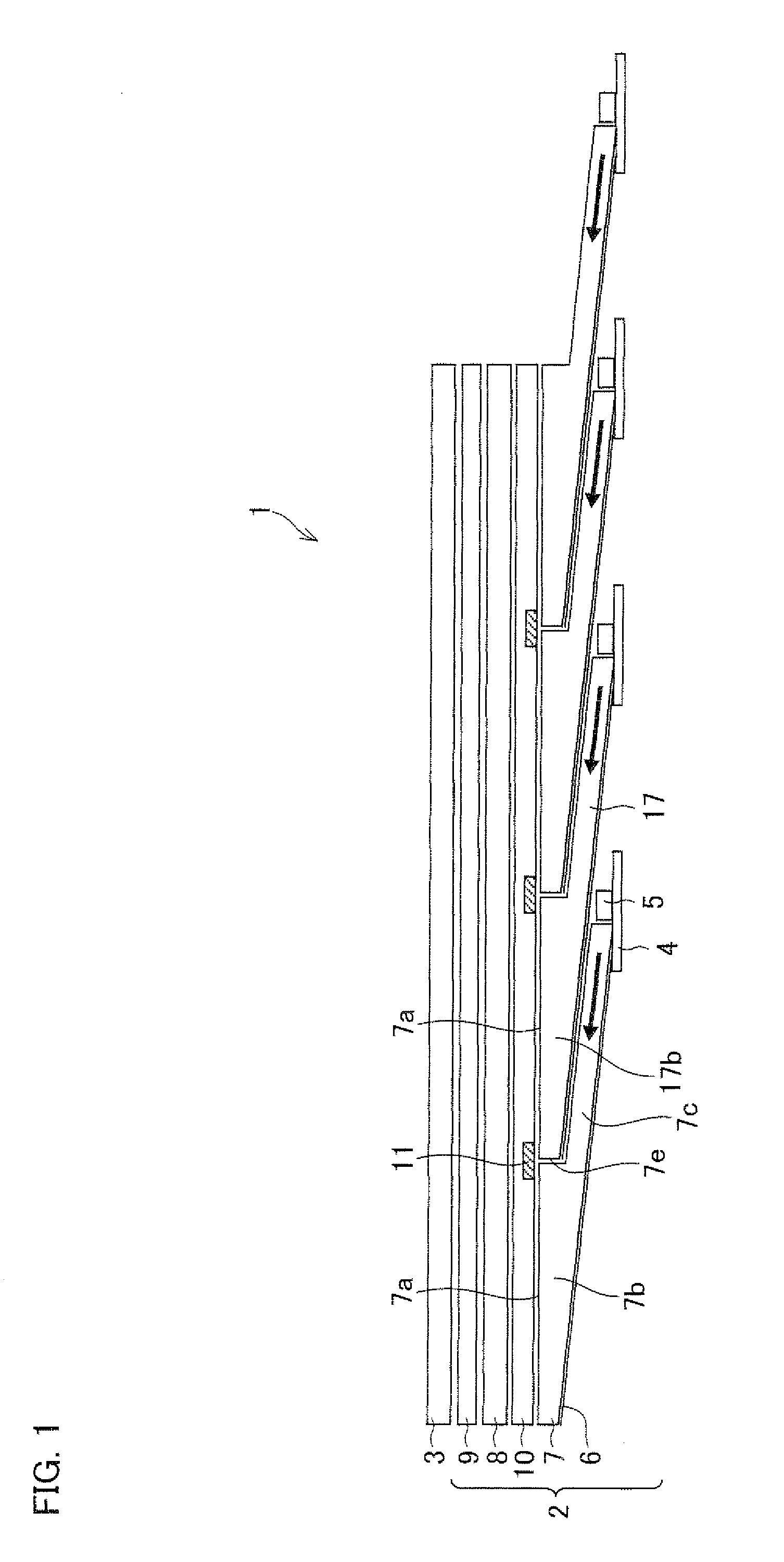
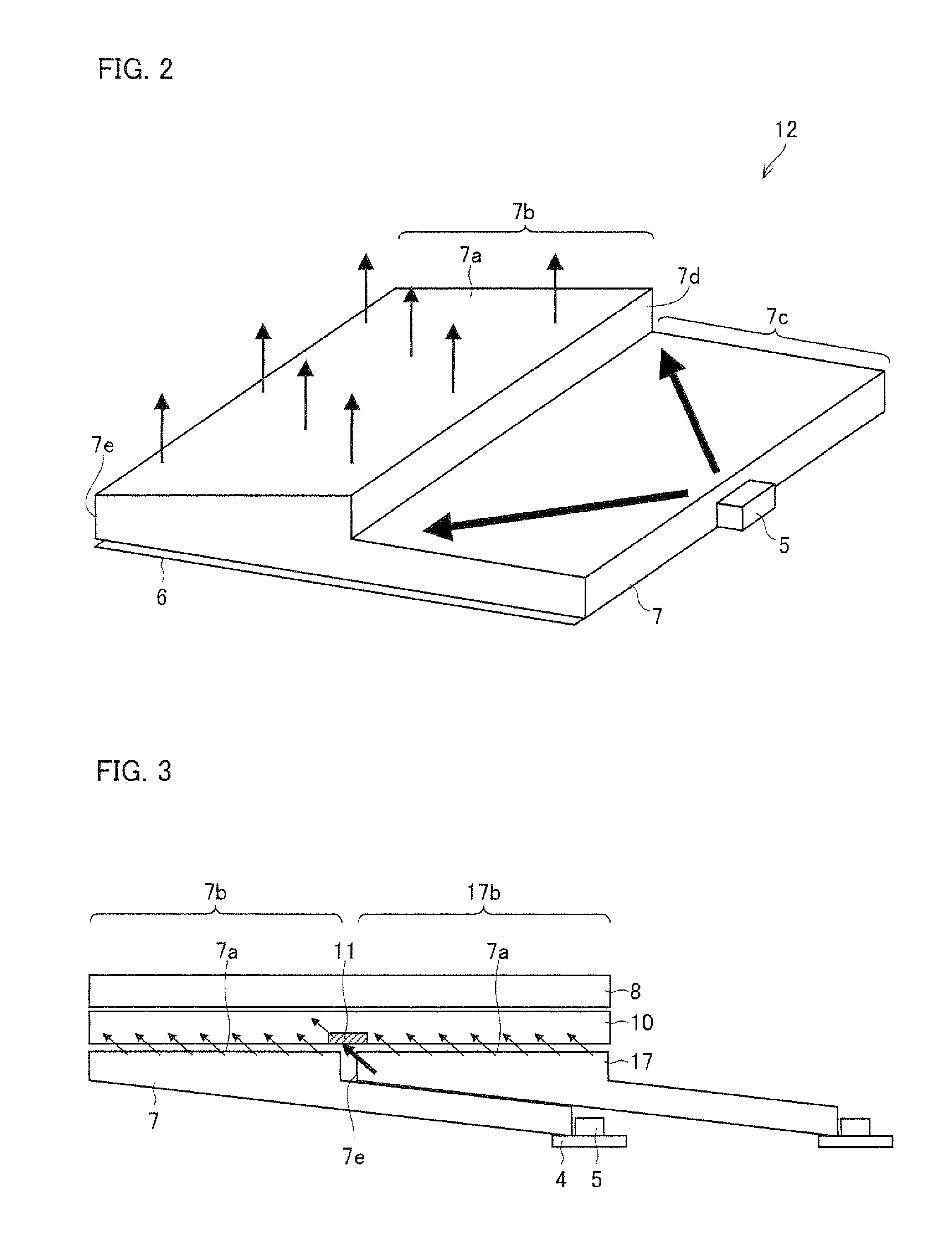
[0069]FIG. 1 is a cross-section view schematically illustrating a configuration of a liquid crystal display device 1 according to the present embodiment. The liquid crystal display device 1 includes: a backlight 2 (illumination device); and a liquid crystal display panel 3 so provided as to face the backlight 2.

[0070]The liquid crystal display panel 3 is similar to a liquid crystal display panel generally used in a conventional liquid crystal display device. For example, the liquid crystal display panel 3 is so configured as to include: an active matrix substrate on which a plurality of thin film transistors (TFTs) are formed; a CF substrate facing the active matrix substrate; and a liquid crystal layer sealed...

embodiment 2

[0100]A second embodiment of the present invention is described below with reference to FIGS. 8 through 15.

[0101]Embodiment 1 above describes a tandem-type backlight. In contrast, the present embodiment describes a tile-type backlight, which includes multiple light guide plates that are arranged in a plane and that do not overlap one another.

[0102]FIG. 8 is a cross-section view schematically illustrating a configuration of a liquid crystal display device 21 according to the present embodiment. FIG. 9 is an enlarged cross-section view of a part of the liquid crystal display device 21. The liquid crystal display device 21 includes: a backlight 22 (illumination device); and a liquid crystal display panel 23 so provided as to face the backlight 22. The liquid crystal display panel 23 has an arrangement similar to an arrangement of the liquid crystal display panel 3 of Embodiment 1.

[0103]The following describes a configuration of the backlight 22 included in the liquid crystal display de...


PUM


Abstract

A backlight (illumination device; 2) of the present invention includes: multiple light sources (5); multiple light guide plates (7, 17, . . . ) for causing surface emission of light from the light sources (5); and a diffusing plate (8) for diffusing light from the light guide plates (7, 17, . . . ), the diffusing plate (8) being provided so as to be separate from and face the light guide plates (7, 17, . . . ). Each of the light guide plates (7, 17, . . . ) includes: a light-emitting section (7b) having a light-emitting surface (7a); and a light guide section (7c) for guiding, to the light-emitting section (7b), light from the light sources (5), a light-emitting section (17b) of the first light guide plate (17) being provided above a light guide section (7c) of the second light guide plate (7) adjacent to the first light guide plate (17). A light amount adjusting section (11) for reducing the amount of light incident on it is provided so as to be separate from the diffusing plate (8) and so that the orthogonal projection of the light amount adjusting section (11) onto the light-emitting region covers the boundary between any adjacent light guide plates (7, 17, . . . ). This allows for production of a tandem-type illumination device having further improved luminance uniformity.

Description

TECHNICAL FIELD[0001]The present invention relates to an illumination device used, for example, as a backlight of a liquid crystal display device, and also relates to a liquid crystal display device including the illumination device.BACKGROUND ART[0002]Liquid crystal display devices have become rapidly popular in place of cathode ray tube (CRT) based display devices in recent years. The liquid crystal display devices have been in widespread use in liquid crystal televisions, monitors, mobile phones, and the like, which take advantage of, e.g., energy saving, thin, and lightweight features of the liquid crystal display devices. One way to further take advantage of such features is to improve an illumination device (i.e., a so-called backlight) which is provided behind the liquid crystal display device.[0003]The illumination devices are roughly classified into a side light type (also referred to as an edge light type) and a direct type. The side light type is configured such that a li...

Claims


Application Information

Patent Timeline
IPC IPC(8): F21V8/00G02F1/13357
CPCG02B6/0021G02F1/133603G02B6/008G02B6/0078
Inventor AJICHI, YUHSAKUMASUDA, TAKESHIKOHTOKU, YUKIHIDE
Owner SHARP KK
Why Eureka
Try Eureka