
Optical scanning device and image forming apparatus

Active Publication Date: 2010-03-11
RICOH KK
View PDF9 Cites 20 Cited by
  • Summary
  • Abstract
  • Description
  • Claims
  • Application Information

AI Technical Summary

Benefits of technology

[0009]It is an object of the present invention to at least

Problems solved by technology

Such an image forming apparatus has a problem that shading may appear on an output image because optical intensities of scanning light beams vary with a change in temperature or over time.
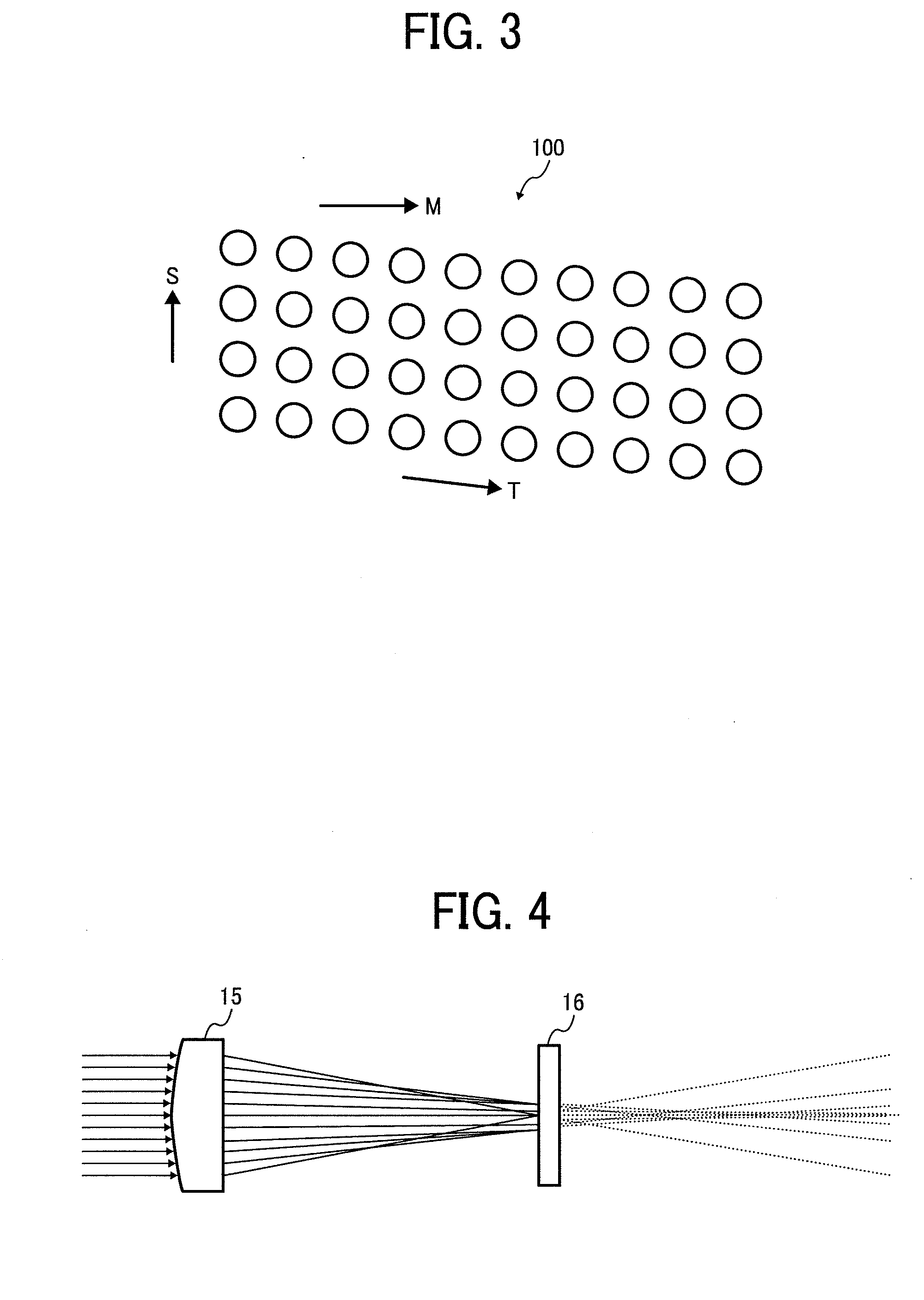
If dust or dirt is attached to a light receiving element or a laser chip, optical intensity of a light beam traveling toward a scanning surface may be affected.
Therefore, it is highly likely that the dust or dirt is attached to a light receiving surface of the light receiving element, resulting in degradation of the monitoring performance.

Method used


Image

  • Optical scanning device and image forming apparatus
  • Optical scanning device and image forming apparatus
  • Optical scanning device and image forming apparatus

Examples


Embodiment Construction

[0038]Exemplary embodiments of the present invention are explained in detail below with reference to the accompanying drawings.

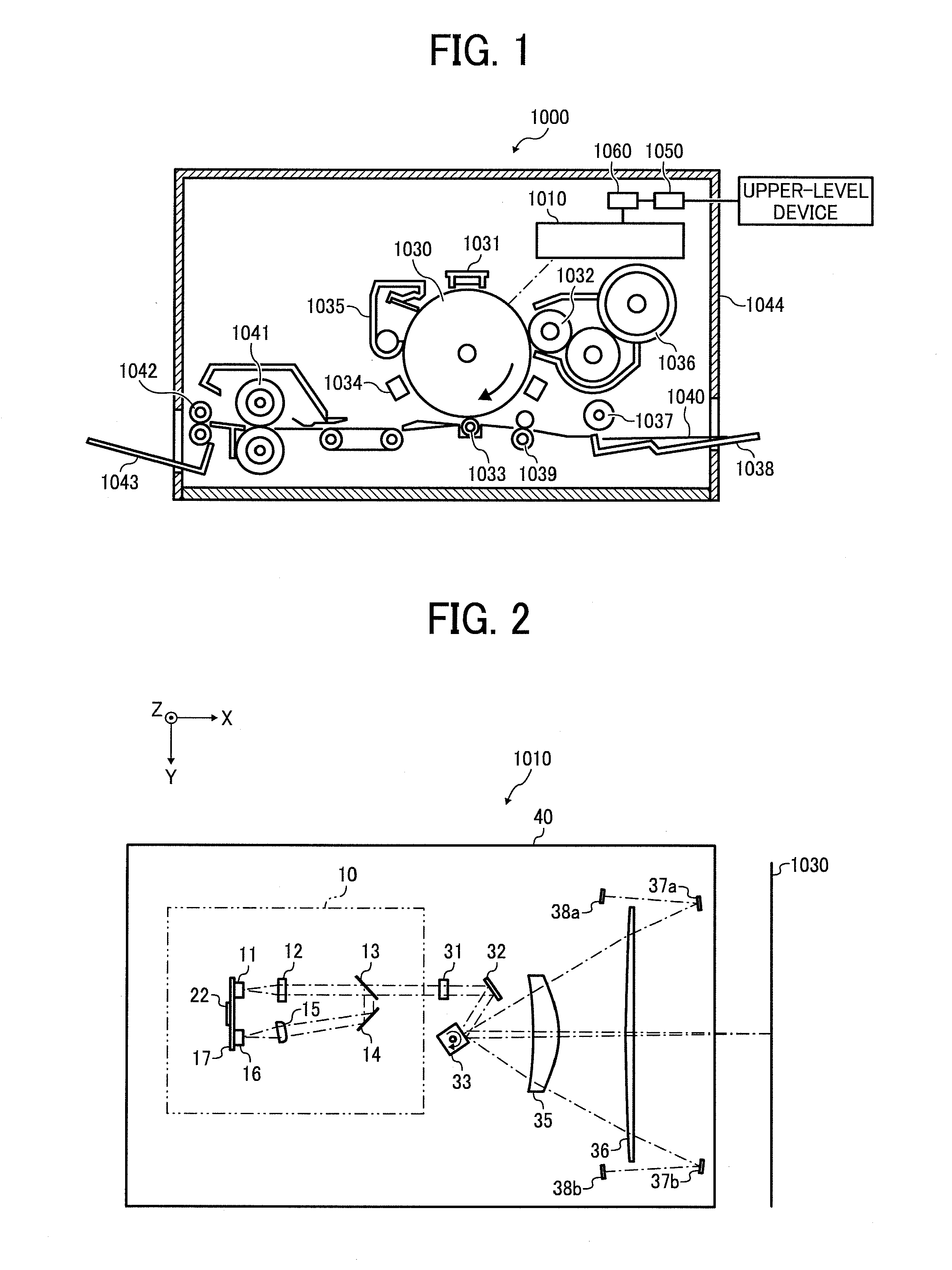
[0039]FIG. 1 is a schematic diagram of a laser printer 1000 as an image forming apparatus according to an embodiment of the present invention. The laser printer 1000 includes an optical scanning device 1010, a photosensitive drum 1030, a charger 1031, a developing roller 1032, a transfer charger 1033, a neutralizing unit 1034, a cleaning unit 1035, a toner cartridge 1036, a sheet feed roller 1037, a sheet feed tray 1038, a pair of registration rollers 1039, a fixing roller 1041, a sheet discharge roller 1042, a copy receiving tray 1043, a communication control unit 1050, a printer control unit 1060 for controlling the above units entirely, and the like. Incidentally, these units are housed in a printer enclosure 1044, and arranged at predetermined positions in the printer enclosure 1044.

[0040]The communication control unit 1050 controls a two-way communicati...


PUM


Abstract

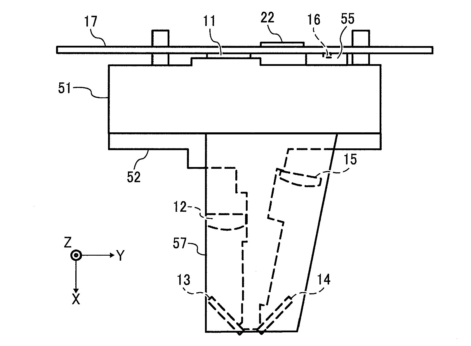
A light beam splitting element that is arranged on an optical path of a light beam emitted from a VCSEL element splits an incident light beam into a first light beam and a second light beam. An optical system focuses the first light beam on the scanning surface and moves an optical spot formed by a focused light beam on the scanning surface in the main scanning direction. A light receiving element that is mounted on a circuit board receives the second light beam. A dust-proof member bridges a space between the circuit board and a circuit-board holding member that holds the circuit board and surrounds the light receiving element.

Description

CROSS-REFERENCE TO RELATED APPLICATIONS[0001]The present application claims priority to and incorporates by reference the entire contents of Japanese Patent Application No. 2008-227709 filed in Japan on Sep. 5, 2008 and Japanese Patent Application No. 2009-067167 filed in Japan on Mar. 19, 2009.BACKGROUND OF THE INVENTION[0002]1. Field of the Invention[0003]The present invention relates to an optical scanning device and an image forming apparatus, and more particularly, to an optical scanning device that scans a scanning surface with a light beam and an image forming apparatus including the optical scanning device.[0004]2. Description of the Related Art[0005]For electrophotographic image recording, an image forming apparatus using a laser as a light source is widely used. Such an image forming apparatus includes an optical scanning device in which a light beam (a scanning light beam) emitted from the light source is deflected by a deflector to scan a surface of a photosensitive drum...

Claims


Application Information

Patent Timeline
IPC IPC(8): G02B26/10
CPCG02B26/127
Inventor MIYAKE, SHINSUKEKUBO, NOBUAKI
Owner RICOH KK
Learn More