Horizontal Copper Patching Assembly

a horizontal copper and assembly technology, applied in metal-working apparatus, electric digital data processing, refrigerating machines, etc., can solve the problem of preventing further use in the deeper portions, and achieve the effect of facilitating port mounting, increasing patching density, and promoting overall cable/system managemen

Inactive Publication Date: 2010-03-11
ORTRONICS INC
View PDF12 Cites 18 Cited by
  • Summary
  • Abstract
  • Description
  • Claims
  • Application Information

AI Technical Summary

Benefits of technology

[0012]Furthermore, in exemplary embodiments, the ports are organized and deployed in defined structures and / or defined configurations, e.g., cassette organizations / arrangements. Such port deployments advantageously facilitate mounting of the ports relative to the tray and promote overall cable / system management. In exemplary embodiments, cassette organizations / arrangements are employed in order to effect plug-and-go capabilities. Thus, in exemplary embodiments of the present disclosure, a patching assembly may include a plurality of cassettes mounted relative to the tray such that the ports are arrayed in a substantially horizontal relationship. The cassettes may be removably / interchangeably installed relative to the tray.
[0013]The presently disclosed patching assemblies and methods present many advantages relative to prior art designs and systems. For example, horizontal deployment of the disclosed ports advantageously increases patching density within a cabinet structure while maintaining port accessibility.

Problems solved by technology

This configuration disadvantageously prevents further use in the deeper portions associated with cavity 12.
Since the port density is limited by this inefficient use of space, a relatively large number of cabinets is often necessary to accommodate the patching needs of data centers.

Method used


Image

  • Horizontal Copper Patching Assembly
  • Horizontal Copper Patching Assembly
  • Horizontal Copper Patching Assembly

Examples


Embodiment Construction

)

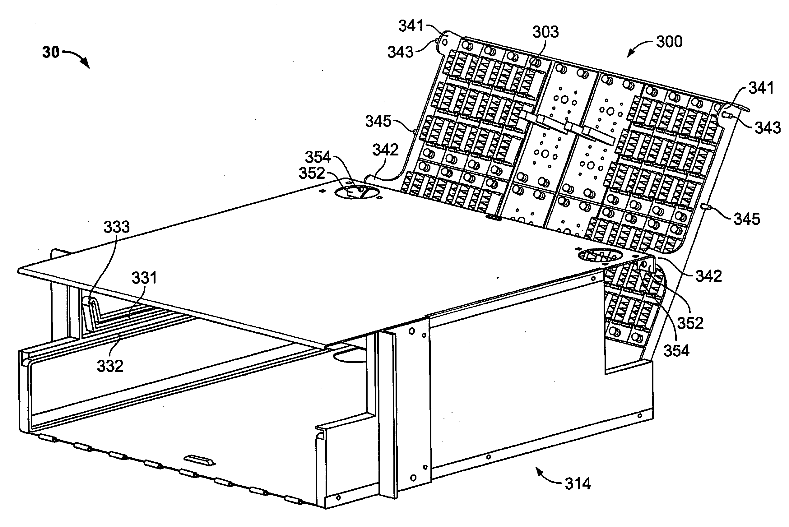
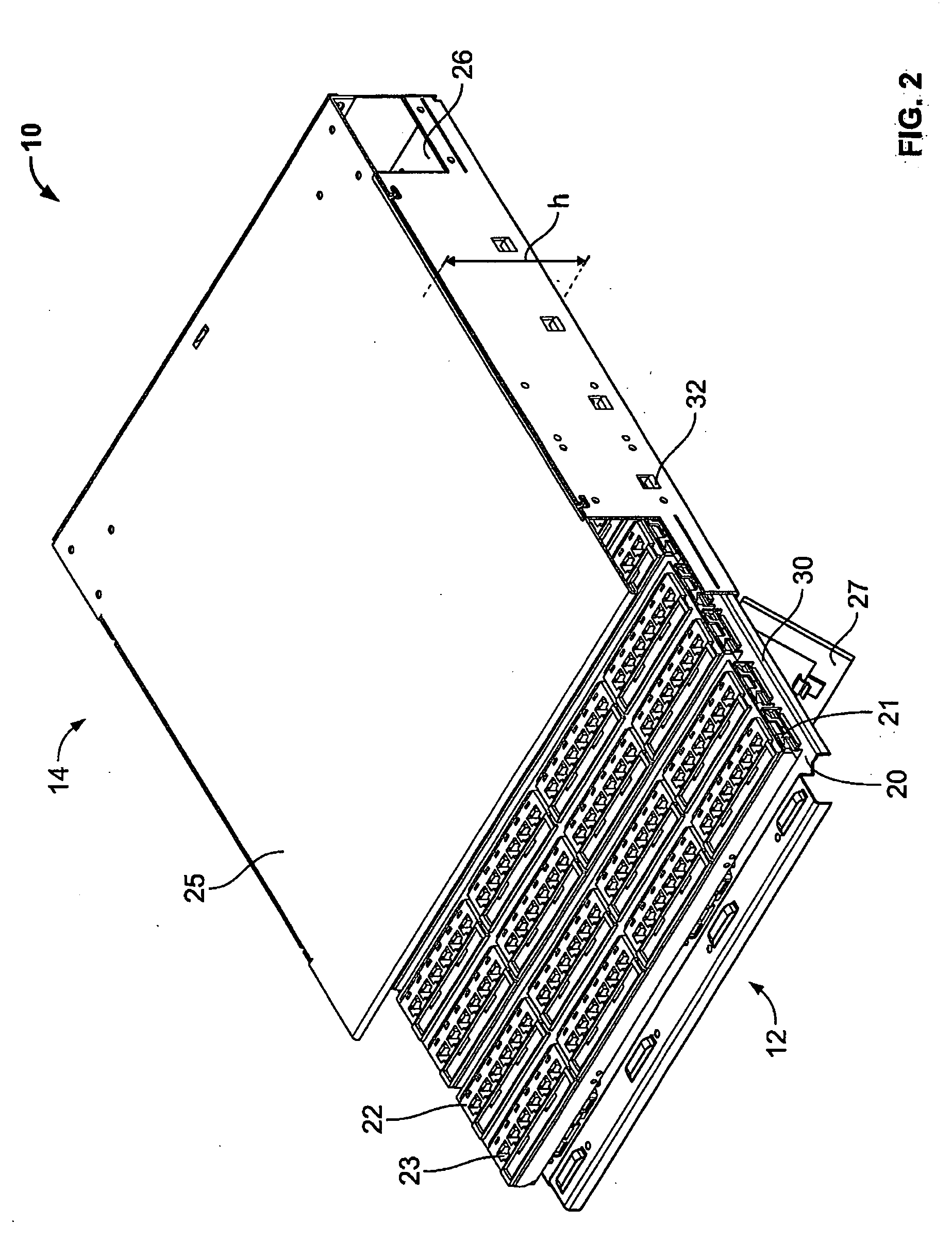
[0020]According to the present disclosure, advantageous assemblies and methods are provided for facilitating copper patching. More particularly, the disclosed assemblies and methods generally involve mounting patch ports in a horizontal plane (horizontally-aligned) with respect to a tray. The disclosed tray is movably positioned with respect to a cabinet enclosure, e.g., via a pivotal or translational (sliding) relationship, thereby providing easy access to the ports. Thus, the horizontally-aligned configuration advantageously increases patching density within a cabinet structure while maintaining port accessibility. In exemplary embodiments, the ports are organized in defined structures / configurations, e.g., cassette casings (with or without plug-and-go capabilities). Such port configurations advantageously facilitate mounting of the ports relative to the tray and promote cable / system management.

[0021]With initial reference to FIGS. 2-3, exemplary embodiments of a horizontally-ali...


PUM

PropertyMeasurementUnit
distanceaaaaaaaaaa
heightaaaaaaaaaa
heightaaaaaaaaaa

Abstract

Assemblies and methods are provided for facilitating copper-wire patching. More particularly, the assemblies and methods involve mounting patch ports arranged along a horizontal plane (horizontally-aligned) with respect to a tray. The tray is movably mounted with respect to a cabinet enclosure, e.g., via a pivotal or translational (sliding) relationship, thereby providing easy access to the ports. The horizontally-aligned configuration advantageously increases patching density within a cabinet structure while maintaining port accessibility.

Description

BACKGROUND[0001]1. Technical Field[0002]The present disclosure relates to assemblies and methods directed to patching assemblies and methods for use in patching of copper-based communication systems.[0003]2. Background Art[0004]Copper patching systems are often used to facilitate networking between switches, servers, storage devices, etc. Patching systems permit users to establish temporary and / or easily modified electrical connections between communication channels, thereby permitting rapid and efficient reconfigurations and / or modifications to network connections in a central location. As shown in the Telecommunication Industry of America (TIA) Standard for data centers, TIA-942, a patch panel interface frequently exists as an integral part of a building's architecture. Due to the relatively large space that data centers can occupy, it is recommended that building architects plan for data center and telecommunication room accommodations early in a design process.[0005]To reduce th...

Claims


Application Information

Patent Timeline
Patent Type & Authority Applications(United States)
IPC IPC(8): H05K7/14B23P11/00
CPCH04Q1/144H04Q1/064Y10T29/49826H04Q1/023H04Q1/025H04Q1/021
Inventor MURANO, ADAMRYNASKI, CHESTER H.
Owner ORTRONICS INC
Why Eureka
Try Eureka