
Mixer Control Device And System

a control device and mixer technology, applied in clay mixing apparatuses, rotary stirring mixers, transportation and packaging, etc., can solve the problems of not providing control of the mixer's rotation speed and rotation time according to the feed amount of dough, not easy to maintain the dough at a constant finishing temperature, and failure to provide any measures for adjusting the process

Inactive Publication Date: 2010-03-11
MIYAZATO YOSHIAKI +1
View PDF16 Cites 9 Cited by
  • Summary
  • Abstract
  • Description
  • Claims
  • Application Information

AI Technical Summary

Benefits of technology

[0074]According to the mixer control device of the present invention, in the manufacturing process of mixing, products of consistent quality can be manufactured continuously by calculating the feed-water temperature based on correction data corresponding to the manufacturing conditions, such as the feed amounts of raw materials, the respective temperatures of the main raw materials, the temperature of the room, and so on.
[0075]According to the mixer control system of the present invention, even if correction data corresponding to the aforementioned temperatures or other conditions are not available in advance, finished products having the target finishing temperature can be manufactured by providing automatic control instructions to the mixer in real time according to changes in the manufacturing conditions, such as the feed amounts of raw materials, the respective temperatures of the main raw materials, the feed-water temperature, the temperature of the room, the humidity of the room's air, and so on.

Problems solved by technology

In mixing the materials for making bread and similar products, which are mainly made of wheat flour, it is not easy to maintain the dough at a constant finishing temperature as changes occur in such conditions as (1) the temperature of the room in which the manufacturing is conducted (hereinafter “the room”), (2) the temperatures of the main raw materials, (3) the temperature of the feed water, (4) the humidity of the room's air, (5) the feed amounts of the materials, and so on.
One example of such an automatic control system of a mixer is disclosed on pages 1-6 in “Control Method and Device for Mixing Bread Dough of Japanese Unexamined Patent Application Publication No. 2001-275550; however, control of the mixer's rotation speed and rotation time according to the feed amount of dough is not provided there.
Furthermore, that example deals only with changes of the mean temperature of bread dough during mixing corresponding to changes in the manufacturing environment and fails to provide any measures for adjusting the process in response to changes of the feed-water temperature or changes in the humidity of the air of the room.
Accordingly, that example contains a problem that the finishing temperatures of the dough vary.

Method used


Image

  • Mixer Control Device And System
  • Mixer Control Device And System
  • Mixer Control Device And System

Examples


embodiment 1

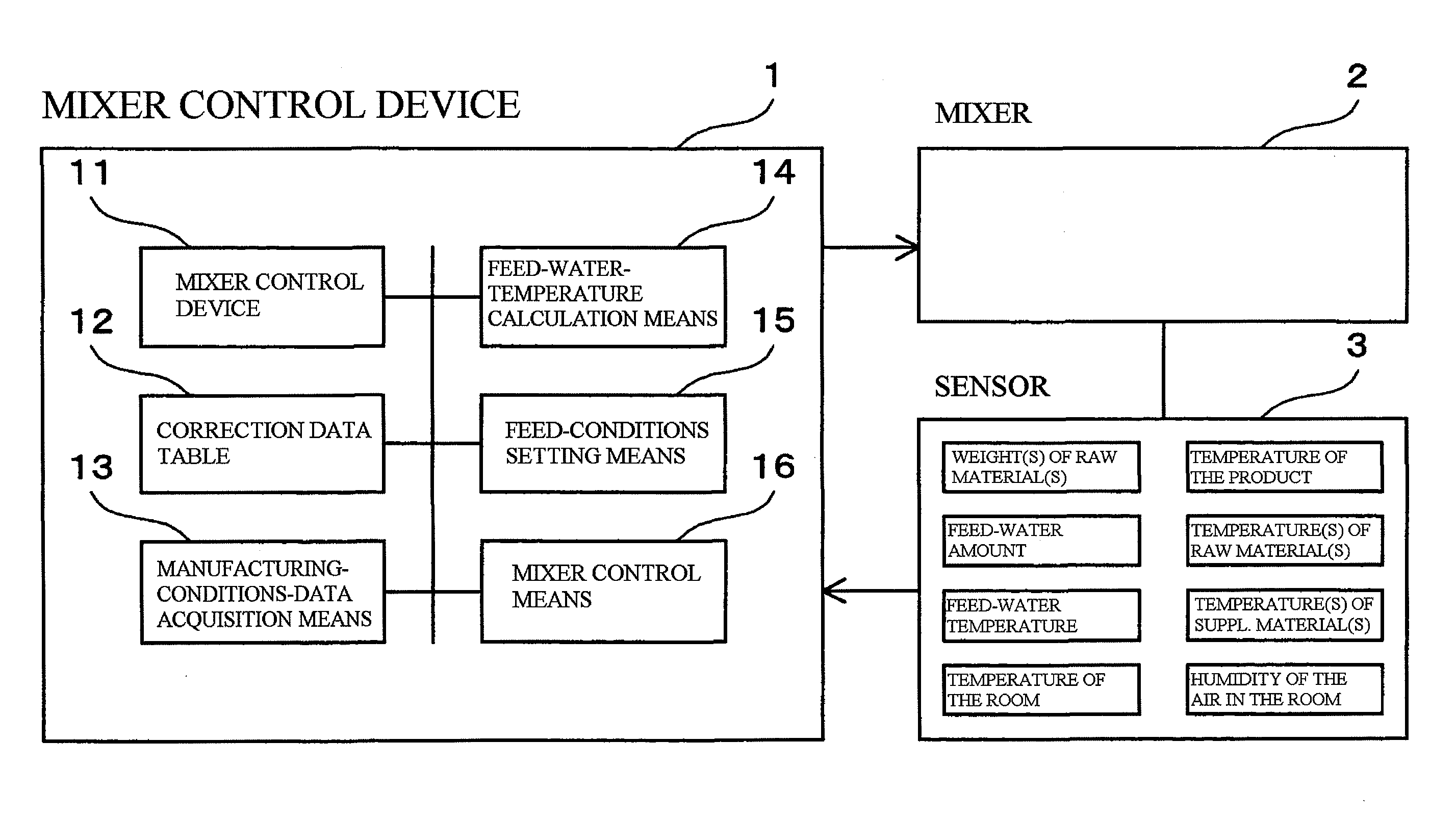
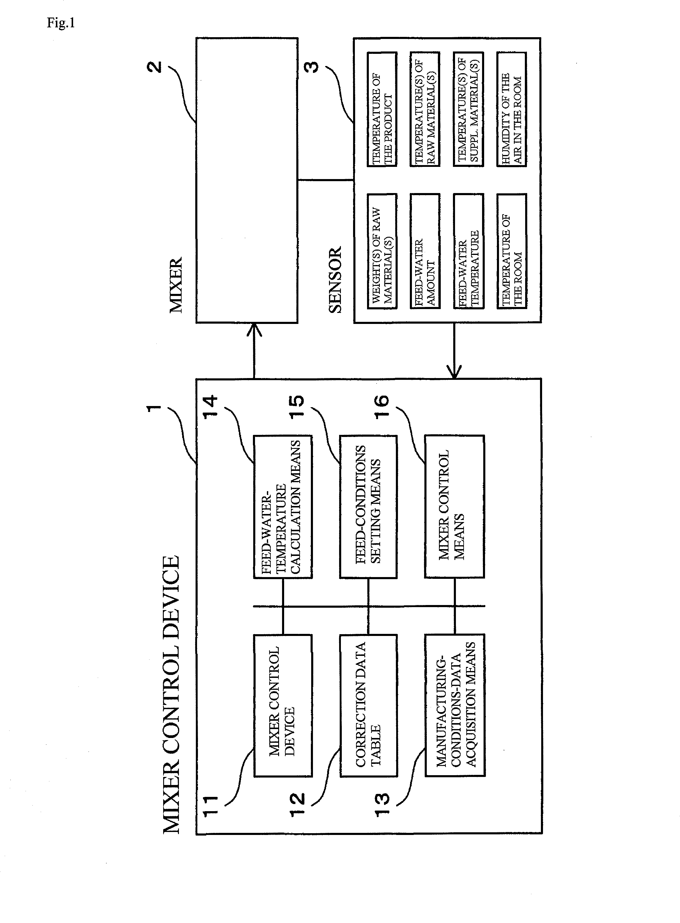
[0085]FIG. 1 is a block diagram of a mixer control device according to an embodiment of the present invention, and in said diagram

[0086]1 is the mixer control device;

[0087]2 is a mixer controlled by the mixer control device 1; and

[0088]3 is a sensor for obtaining the temperatures of the raw materials, the temperature of the room, and the temperature of the product, along with changes in such temperatures. Said sensor obtains the temperature of each raw material before feeding, the product's temperature and changes thereof after feeding, the temperature(s) of supplementary material(s) added to the main raw materials, the ambient environment's temperature (temperature of the room), the humidity of the manufacturing environment's air (room humidity), and so on. In addition, the sensor also monitors the weight of the raw materials, the feed-water amount, and the temperatures thereof in the process of manufacturing the product.

[0089]Although the mixer control device 1 can be configured b...

embodiment 2

[0097]FIG. 3 is a block diagram of a mixer control system according to another embodiment of the present invention. The configuration and operation thereof will now be explained, referring to that drawing.

[0098]As shown in FIG. 3, the mixer control system 100 includes

[0099]a manufacturing terminal 4 for providing instructions for manufacturing products, including semi-manufactured products;

[0100]a mixer 2 for manufacturing such products;

[0101]a control unit 10, which is connected to the control management unit 30 for controlling the mixer 2;

[0102]a sensor 3, which is connected to the control unit 10, and which obtains manufacturing-conditions data, including the feed-water temperature, the temperature of the product being manufactured, and the humidity of the room, along with changes in such data as they occur; and

[0103]a control management unit 30, which (1) is connected to the manufacturing terminal 4 via the Internet 5, (2) creates control data for the mixer 2, based on the manuf...


PUM

PropertyMeasurementUnit
Temperatureaaaaaaaaaa
Weightaaaaaaaaaa
Timeaaaaaaaaaa

Abstract

A mixer control device capable of manufacturing products of consistent quality without skilled personnel is provided. Said mixer control device includes: (1) a sensor 3 for obtaining manufacturing-conditions data, including at least the temperatures of the raw materials, the temperature of the room in which the manufacturing occurs, and the temperature of the product being manufactured, along with changes in such manufacturing-conditions data; (2) a manufacturing-conditions-data acquisition means 13 for obtaining and maintaining the manufacturing-conditions data from said sensor; (3) correction data 12 for correcting the feed-water temperature based on said obtained manufacturing-conditions data; (4) a feed-conditions setting means 15 for setting the feed conditions, including at least the mixing time of the mixer and a product's feed-water temperature, according to the feed amounts of the raw materials based on said correction data; and (5) a mixer control means 16 for controlling said mixer, based on said feed conditions.

Description

TECHNICAL FIELD[0001]The present invention relates to a mixer control device and a system for controlling a mixer based on manufacturing instructions data for each specified product and data concerning particular manufacturing conditions relating to a product, including any semi-manufactured product that is used in manufacturing the product.BACKGROUND ART[0002]In mixing the materials for making bread and similar products, which are mainly made of wheat flour, it is not easy to maintain the dough at a constant finishing temperature as changes occur in such conditions as (1) the temperature of the room in which the manufacturing is conducted (hereinafter “the room”), (2) the temperatures of the main raw materials, (3) the temperature of the feed water, (4) the humidity of the room's air, (5) the feed amounts of the materials, and so on. Under such conditions, the automatic control of mixing so as to maintain the dough at a constant finishing temperature—by means of adjusting the mixer...

Claims


Application Information

Patent Timeline
IPC IPC(8): A21C1/00
CPCA21C1/145B01F15/00285B01F15/00253B01F15/00207B01F35/213B01F35/2209B01F35/2202
Inventor MIYAZATO, YOSHIAKIMAKITA, YUJI
Owner MIYAZATO YOSHIAKI
Learn More