
Multichannel Optical Transport Network Time Domain Reflectometry Calibration

Active Publication Date: 2010-03-11
MACOM CONNECTIVITY SOLUTIONS LLC
View PDF1 Cites 4 Cited by
  • Summary
  • Abstract
  • Description
  • Claims
  • Application Information

AI Technical Summary

Benefits of technology

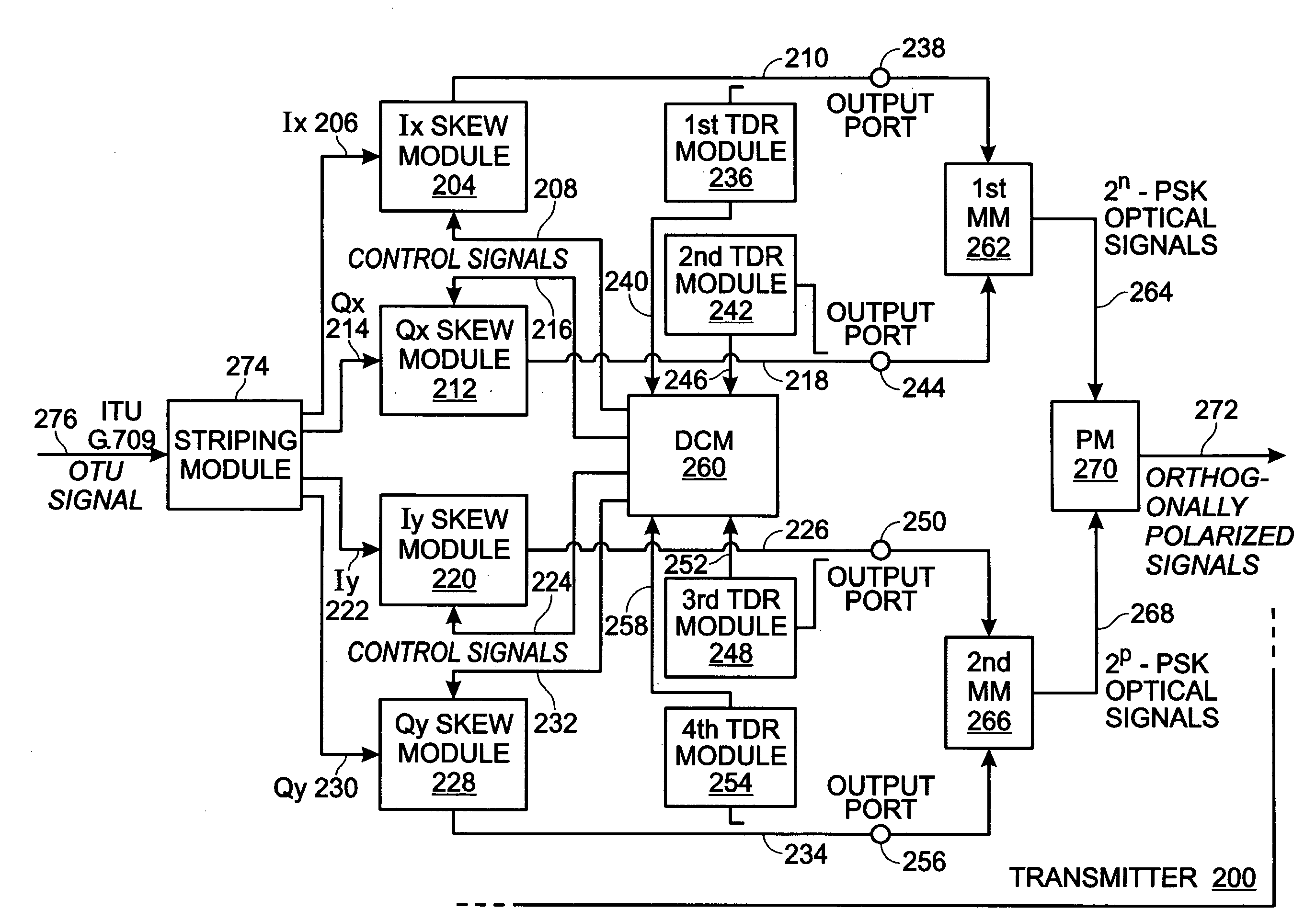
[0008]Accordingly, a method is provided for controlling time delay in a multichannel optical transport network (OTN) transmission device using time domain reflectometry (TDR). The method accepts a pair of 2n-phase shift keying (2n-PSK) modulated signals via Ix and Qx electrical signal paths, where n>1. Likewise, a pair of 2p-PSK modulated signals are accepted via Iy and Qy electrical signal paths where p>1. Using TDR modules, signal reflections are measured from an output port for each signal path. The method minimizes time delay differences in the signal reflections for the Ix, Qx, Iy, and Qy signals paths by using the signal reflection measurements to adjust time delay modules in each signal path.

Problems solved by technology

However, the need for faster signal speeds means that return to zero (RZ), non-return to zero (NRZ), and phase-shift keying (PSK) modulation techniques (1 bit per symbol) are no longer suitable.
Any skew (differential time delay) experienced in the modulation of the transmitted signal is translated to the receiver, making the recovery of a serial stream from parallel streams difficult.

Method used


Image

  • Multichannel Optical Transport Network Time Domain Reflectometry Calibration
  • Multichannel Optical Transport Network Time Domain Reflectometry Calibration
  • Multichannel Optical Transport Network Time Domain Reflectometry Calibration

Examples


Embodiment Construction

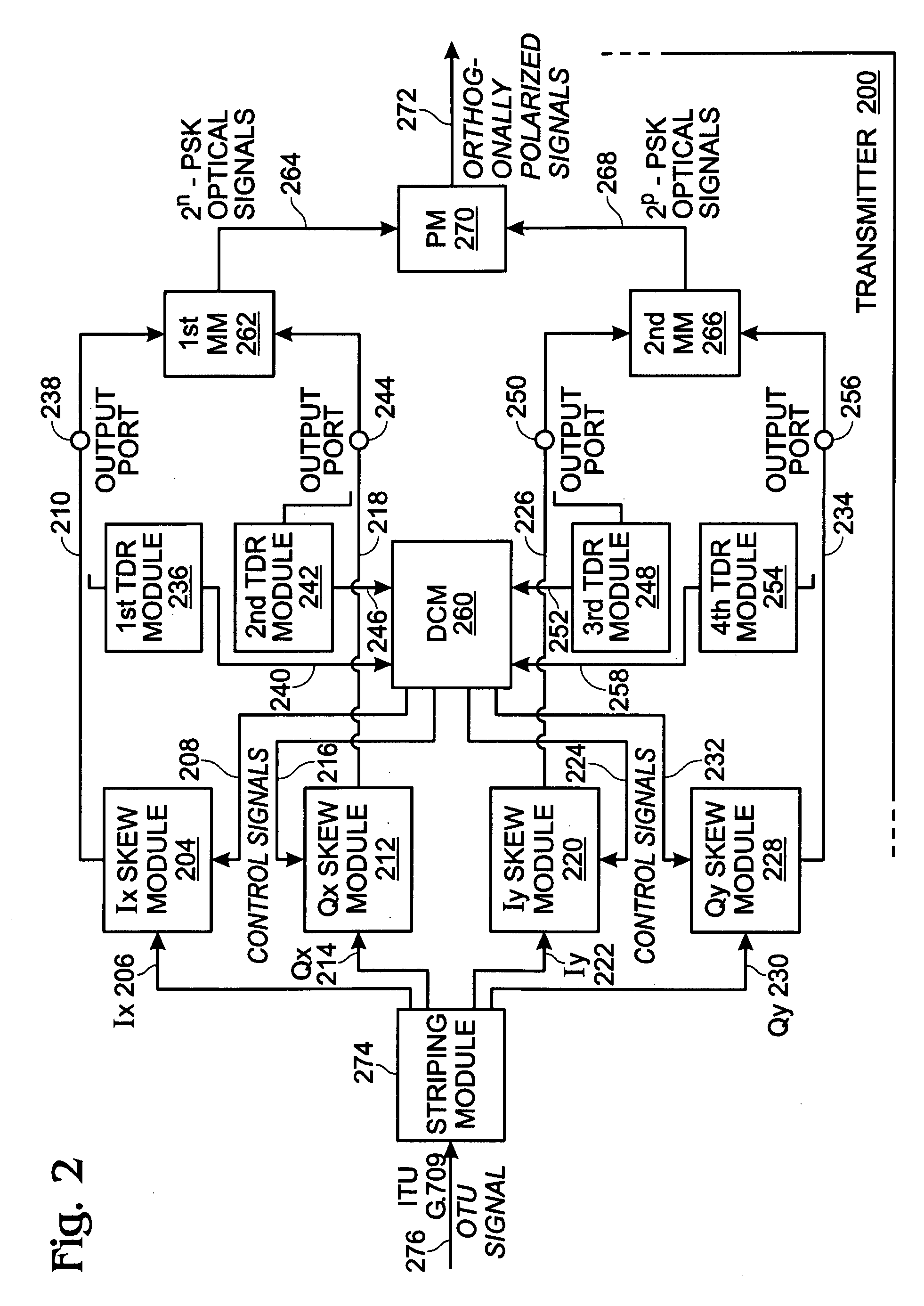
[0015]FIG. 2 is a schematic block diagram of a system for controlling time delay in a multichannel optical transport network (OTN) transmission device 200 using time delay reflectometry measurements. The system 202 comprises an Ix skew module 204 having an input on line 206 to accept an Ix signal from a pair of 2n-phase shift keying (2n-PSK) modulated signals, where n>1. In one aspect, n=2. However, the system is not limited to any particular value of n. The Ix skew module 204 has a control port on line 208 and an output on line 210 to supply the Ix signal delayed in time in response to signals received at the control port. A Qx skew module 212 has an input on line 214 to accept a Qx signal from the pair of 2n-PSK modulated signals. The Qx skew module 212 has a control port on line 216 and an output on line 218 to supply the Qx signal delayed in time in response to signals received at the control port.

[0016]An Iy skew module 220 has an input on line 222 to accept an Iy signal from a...


PUM


Abstract

A system and method are provided for controlling time delay in a multichannel optical transport network (OTN) transmission device using time domain reflectometry (TDR) measurements. The method accepts a pair of 2n-phase shift keying (2n-PSK) modulated signals via Ix and Qx electrical signal paths, where n>1. Likewise, a pair of 2p-PSK modulated signals are accepted via Iy and Qy electrical signal paths where p>1. Using TDR modules, signal reflections are measured from an output port for each signal path. The method minimizes time delay differences in the signal reflections for the Ix, Qx, Iy, and Qy signals paths by using the signal reflection measurements to adjust time delay modules in each signal path.

Description

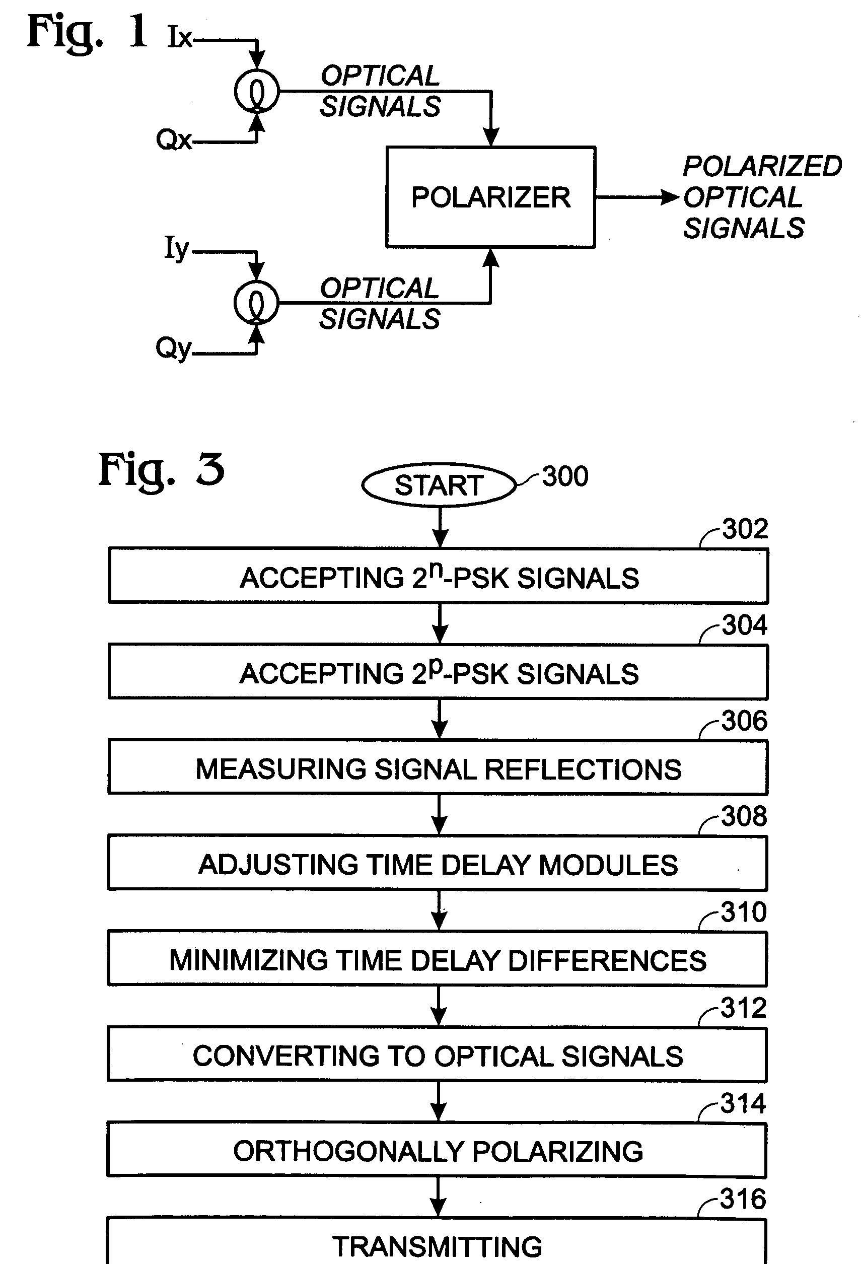
BACKGROUND OF THE INVENTION[0001]1. Field of the Invention[0002]This invention generally relates to signal communications and, more particularly, to a system and method that uses time domain reflectometry measurements to calibrate for skew errors in a multichannel Optical Transport Network (OTN) transmitter.[0003]2. Description of the Related Art[0004]100 gigabit per second (Gbps) OTN protocols are being developed where the OTN streams are carried in a “parallel fashion” at a bit-rate greater than 100 Gbps. Until recently, optical signals have been carried using modulations techniques carrying 1 bit per symbol. However, the need for faster signal speeds means that return to zero (RZ), non-return to zero (NRZ), and phase-shift keying (PSK) modulation techniques (1 bit per symbol) are no longer suitable.[0005]FIG. 1 is a schematic diagram depicting a system for the transmission of high speed signals (40 / 100 Gbps and above) using multiplexed orthogonal optical polarization, with 2 bits...

Claims


Application Information

Patent Timeline
IPC IPC(8): H04J14/08
CPCH04B10/071H04J14/06H04J3/1652H04J3/0682
Inventor CONROY, KEITHACIKEL, OMERCAGGIONI, FRANCESCO
Owner MACOM CONNECTIVITY SOLUTIONS LLC
Learn More