Scanning device

a scanning device and scanning technology, applied in the field of scanning devices, can solve the problems of difficult correction and unstable display of images, and achieve the effects of stable image display, reduced time delay in generating second signal elements, and improved accuracy

Active Publication Date: 2021-05-27
HAMAMATSU PHOTONICS KK
View PDF0 Cites 0 Cited by
  • Summary
  • Abstract
  • Description
  • Claims
  • Application Information

AI Technical Summary

Benefits of technology

[0012]In the scanning device according to the aspect of the present disclosure, the control unit may generate the second signal element to correspond to the first signal element in a current one cycle period in the first drive signal. Alternatively, the control unit may generate the second signal element to correspond to the first signal element in an immediately previous one cycle period in the first drive signal. According to this, time delay when generating the second signal element can be minimized.
[0013]In the scanning device according to the aspect of the present disclosure, the MEMS mirror mechanism may include a first movable unit provided with the mirror, a second movable unit that supports the first movable unit to be swingable with respect to the first axial line as a central line, a support unit that supports the second movable unit to be swingable with respect to the second axial line as a central line, a drive coil that is provided in the second movable unit, and a magnet that generates a magnetic field acting on the drive coil. The electromagnetic drive type MEMS mirror mechanism is susceptible to a variation of an ambient temperature or the like, and thus repetition of generation of the second signal element as described above is particularly effective.
[0014]In the scanning device according to the aspect of the present disclosure, the light source may emit the laser light for projection display, and in a case where m times (m is an integer of two or greater) of reciprocation of an irradiation region in a first direction and one time of reciprocation of the irradiation region in a second direction correspond to each other, the control unit may generate the first drive signal and the second drive signal so that an image of one frame or two frames is formed by the m times of reciprocation of the irradiation region in the first direction and the one time of reciprocation of the irradiation region in the second direction. As described above, it is possible to suppress occurrence of a deviation in the corresponding relationship between the first drive signal and the second drive signal, and thus, in this case, stable image display is possible.
[0015]In the scanning device according to the aspect of the present disclosure, the control unit may control the light source so that the laser light is modulated in correspondence with a position of the irradiation region. According to this, image display with higher quality is possible.
[0016]In the scanning device according to the aspect of the present disclosure, the control unit may repeat generation of the second signal element while fluctuating a frame rate. According to this, it is possible to easily and reliably repeat generation of the second signal element.
[0017]According to the present disclosure, it is possible to provide a scanning device capable of realizing stable scanning with laser light.

Problems solved by technology

However, for example, in a case where a mirror is caused to be resonated by the horizontal drive signal, when a resonance frequency of the mirror varies in one frame due to a variation of an ambient temperature or the like, in the technology described in Patent Literature 1, it is difficult to correct a deviation that occurs in a corresponding relationship between the horizontal drive signal and the vertical drive signal until the one frame is terminated, and as a result, there is a concern that display of an image may be unstable.

Method used


Image

  • Scanning device
  • Scanning device
  • Scanning device

Examples


modification example

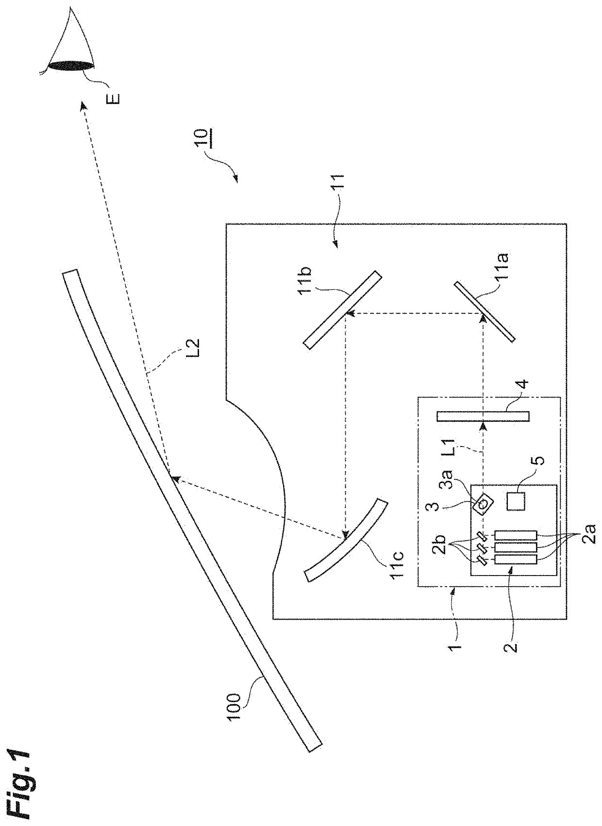
[0081]The present disclosure is not limited to the one embodiment. For example, the light source 2 is not limited to a light source that uses a laser diode (semiconductor laser), and may be a light source that uses a surface-emitting laser, an SLD (super luminescent diode), or the like. In addition, a drive type of the MEMS mirror mechanism 3 is not limited to the electromagnetic drive type, and may be an electrostatic drive type, a piezoelectric drive type, a thermal drive type, or the like. In addition, the light diffusion unit 4 is not limited to the transmission type microlens array, and may be reflection type microlens array, a micro mirror array, a diffraction lattice, a fiber optic plate, or the like.

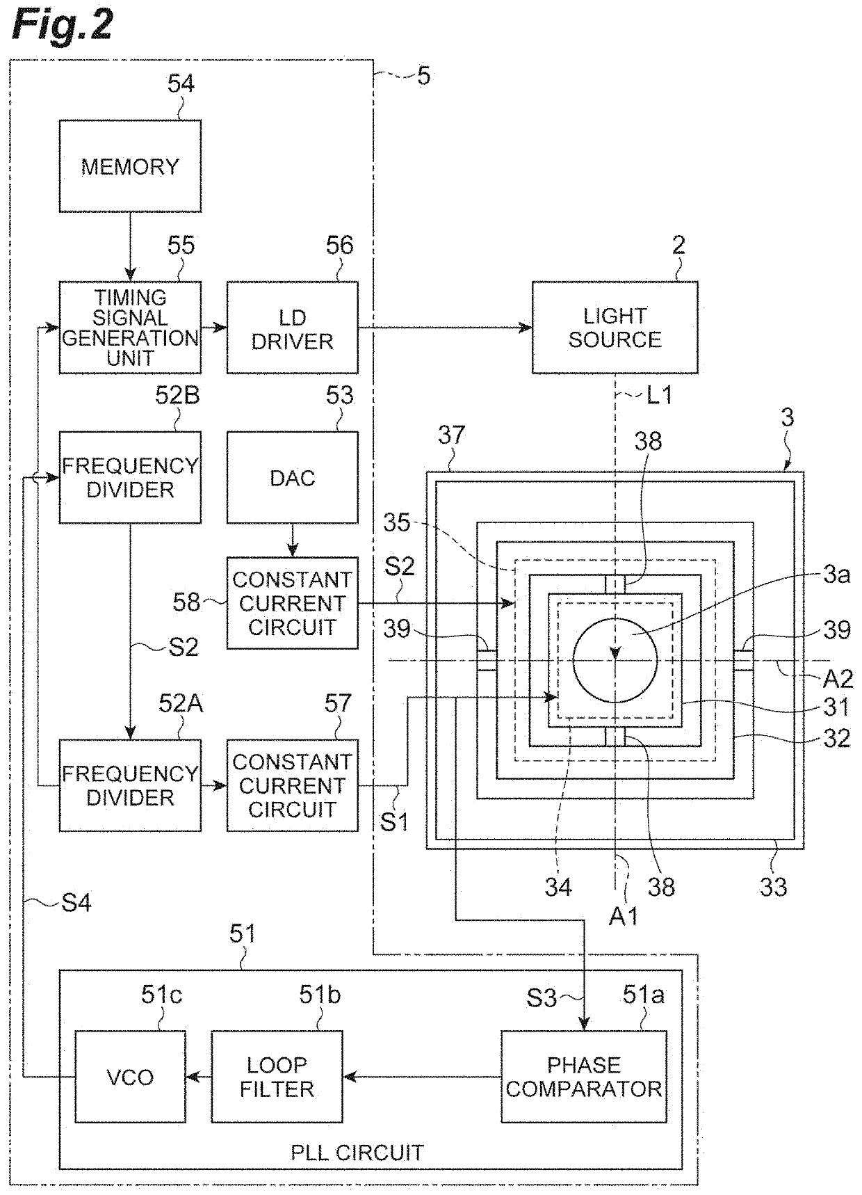
[0082]In addition, as illustrated in FIG. 10, the MEMS mirror mechanism 3 may further include an electromotive force monitoring coil 36. The electromotive force monitoring coil 36 is provided in the first movable unit 31 to be located on an inner side of the first drive coil 34. ...


PUM


Abstract

A scanning device includes an MEMS mirror mechanism that swings a mirror with respect to a first axial line as a central line and swings the mirror with respect to a second axial line as a central line, and a control unit that generates a first drive signal for swinging the mirror with respect to the first axial line as a central line and a second drive signal for swinging the mirror with respect to the second axial line as a central line. In a lighting-on period in which a light source emits laser light in one swing of the mirror with respect to the second axial line as a central line, the control unit generates the first drive signal and the second drive signal by repeating a process of generating N pieces (N is an integer of two or greater) of second signal elements which respectively constitute the second drive signal with respect to a first signal element in a ½ cycle period in the first drive signal.

Description

TECHNICAL FIELD[0001]The present disclosure relates to a scanning device.BACKGROUND ART[0002]As a scanning device, for example, a scanning device that performs scanning with laser light by using a MEMS (micro electro mechanical systems) mirror mechanism to display an image is known. In the scanning device, for example, an image of one frame or two frames is formed by m times of reciprocation (m: an integer of two or greater) of an irradiation region of laser light in a horizontal direction, and one time of reciprocation of the irradiation region of the laser light in a vertical direction. Patent Literature 1 (Japanese Unexamined Patent Publication No. 2006-276634) discloses a technology in which synchronization is performed at the time of initiating one frame and at the time of terminating one frame between a horizontal drive signal and a vertical drive signal for driving the MEMS mirror mechanism.SUMMARY OF INVENTION[0003]However, for example, in a case where a mirror is caused to ...

Claims


Application Information

Patent Timeline
Patent Type & Authority Applications(United States)
IPC IPC(8): G02B26/08G02B26/10
CPCG02B26/0833G02B26/101
Inventor SAKURAI, NAOTONOZAKI, MAKOTO
Owner HAMAMATSU PHOTONICS KK
Why Eureka
Try Eureka