Composite Blade and Method of Manufacture

a technology of composite blades and blades, which is applied in the direction of blade accessories, machines/engines, waterborne vessels, etc., can solve the problems of troublesome attachment of composite blades to metal disks, and inherently fret-resistant composite materials

Inactive Publication Date: 2010-03-11
SIEMENS ENERGY INC
View PDF33 Cites 23 Cited by
  • Summary
  • Abstract
  • Description
  • Claims
  • Application Information

AI Technical Summary

Problems solved by technology

However, composite materials are not inherently fret-resistant, and the attachment of a composite blade to a metal disk is problematic.

Method used


Image

  • Composite Blade and Method of Manufacture
  • Composite Blade and Method of Manufacture
  • Composite Blade and Method of Manufacture

Examples


Embodiment Construction

[0016]The term composite material as used herein refers to a material comprising at least two elements working together to produce material properties that are different from those elements on their own. In practice, most composites comprise a bulk material (the “matrix”) and a reinforcement material added primarily to increase the strength and stiffness of the matrix. This reinforcement material is usually in fiber form.

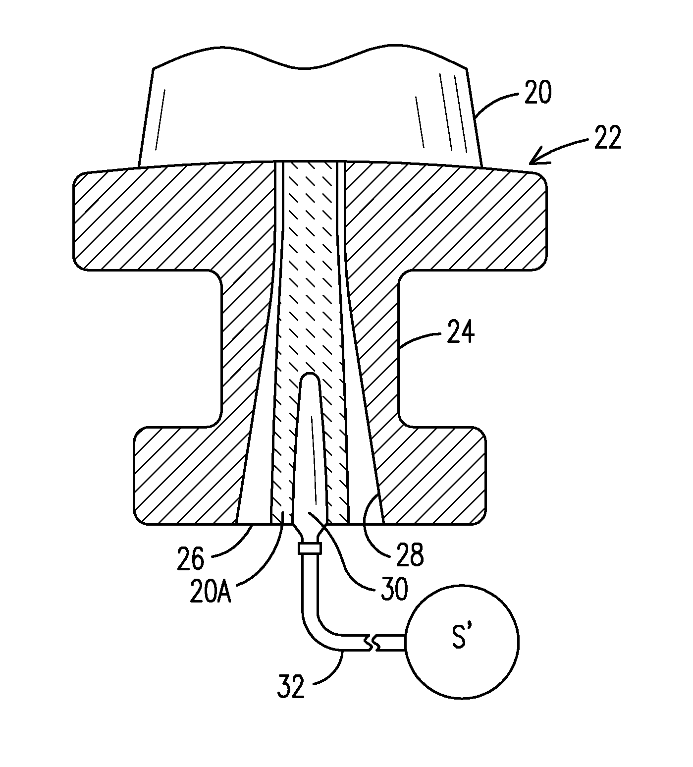
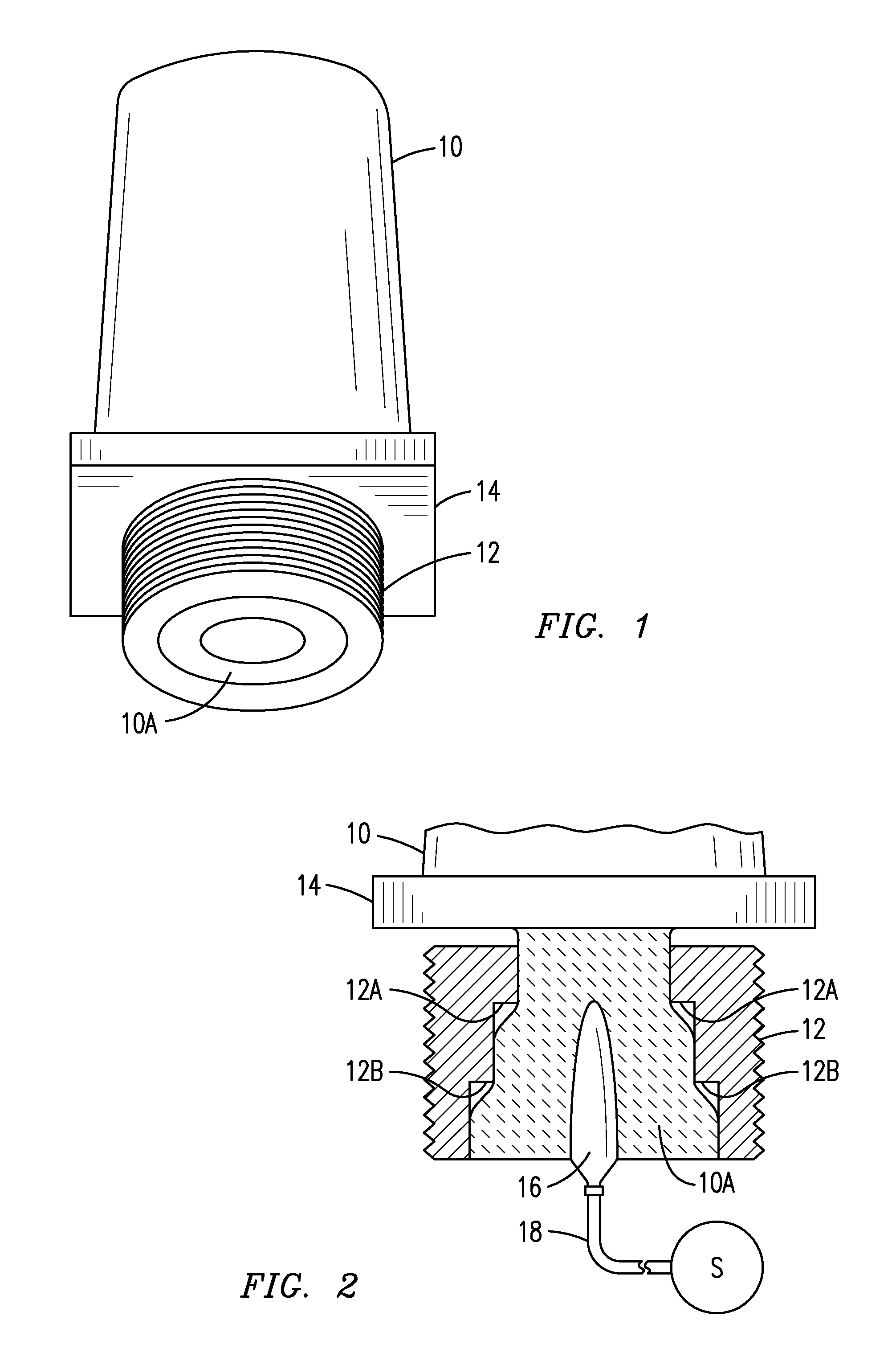
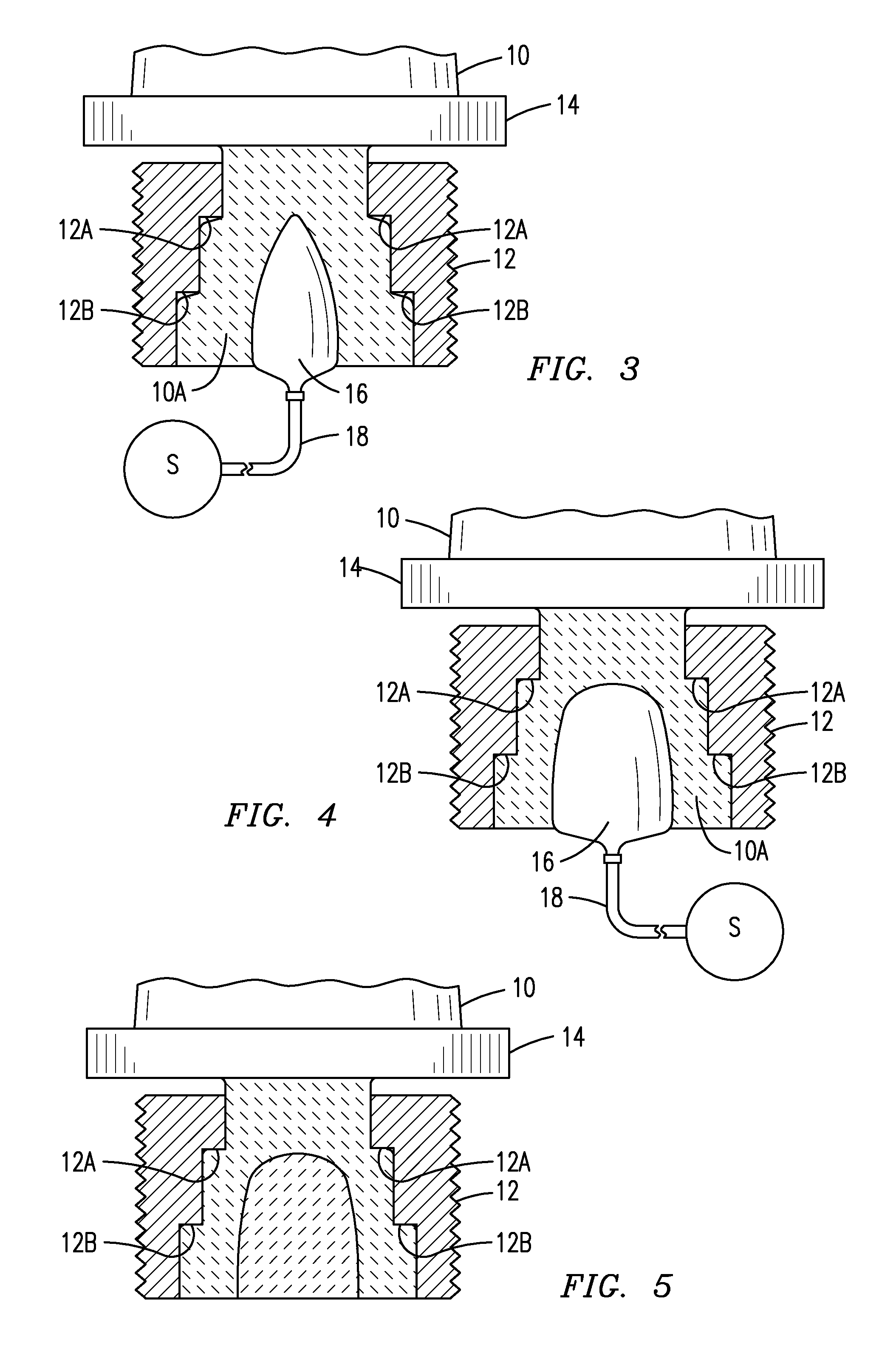
[0017]The present inventor has innovatively designed a composite blade and blade attachment scheme that is compatible with a standard metal blade holder / disk attachment geometry. The present design may be used for new applications, and advantageously may also be used to retrofit existing metal blades with like-in-kind composite blades without the need for a modification of the disk. When attaching composite structures, such as turbine blades, to conventional blade attachments (whether threaded or T-root) it is necessary to construct a blade that is formable and bond...


PUM

PropertyMeasurementUnit
thicknessaaaaaaaaaa
metallicaaaaaaaaaa
shapeaaaaaaaaaa

Abstract

A method of making a composite blade that is attachable to a rotating shaft using a conventional metal blade attachment. A blade is formed from a composite material with a blade root at one end thereof. A metallic member having an external shape conforming to a conventional metal blade root is shaped with an interior cavity having an opening for receipt of the blade root. Before the composite material is fully cured, a bladder is formed into or is inserted into an end of the blade root and inflated, thereby forcing the composite material into intimate contact with the interior cavity of the metallic member, thereby ensuring a fret-free interface upon final curing of the composite material. The interior cavity of the metallic member may be shaped or surfaced to improve the load carrying capability there between.

Description

FIELD OF THE INVENTION[0001]This invention generally relates to a blade for a rotating apparatus, and in particular to a method of attaching a composite blade to a rotating apparatus using a conventional metal blade attachment geometry.BACKGROUND OF THE INVENTION[0002]Metal blades are formed with an airfoil section for interface with a working fluid and a root section for attachment of the blade to a rotating metal disk. The root section may have any of a variety of known shapes (for example, dovetail, T-root, Christmas or fir tree, or a threaded attachment), but in each instance, the root section conforms to a corresponding attachment shape on the disk with a desired degree of looseness to facilitate the installation and removal of the blade. Slight movement between a metal blade root section and the corresponding attachment geometry on the disk during operation of the apparatus is accommodated by the inherent fretting resistance of the blade and disk materials.[0003]Composite blad...

Claims


Application Information

Patent Timeline
Patent Type & Authority Applications(United States)
IPC IPC(8): F04D29/34B21D53/78
CPCF04D29/023F04D29/34Y10T29/49316Y10T29/49337Y10T29/49336F04D29/388B29C43/3642B29C66/02245B29C66/1222B29C66/1226B29C66/12822B29C66/12841B29C66/30322B29C66/5324B29C66/612B29C66/634B29C66/71B29C66/721B29C66/7212B29C66/72141B29C66/73161B29C66/73753B29C66/7394B29C66/742B29C66/81455B29D99/0025B29L2031/08F01D5/147F01D5/282F01D5/284F01D5/30F05D2230/23F05D2300/6033B29K2309/08B29K2063/00
Inventor JONES, WILLIAM F.
Owner SIEMENS ENERGY INC
Why Eureka
Try Eureka