Motor and compressor

Inactive Publication Date: 2010-03-11
DAIKIN IND LTD
View PDF4 Cites 10 Cited by
  • Summary
  • Abstract
  • Description
  • Claims
  • Application Information

AI Technical Summary

Benefits of technology

[0024]As apparent from the above description, according to the motor of the invention, there can be realized an inner rotor type motor capable of easily ensuring enough flow passage cross-sectional area for the fluid passages extending through the rotor in the axial direction with a simple construction without decreasing the rigidity as well as without obstructing the flow of magnetic flux.
[0025]Also, according to the motor of one embodiment, by providing fluid passages through the rotor core radially inside central portions of magnets, it becomes achievable to ensure large refrigerant passages.
[0026]Also, according to the motor of one embodime

Problems solved by technology

In this case, the rivets 333 and the holes 334, which are placed in a region of high magnetic flux density, obstruct the flow of magnetic flux, causing decreases of torque and efficiency.
Further, an attempt to suppress the decreases of torque and efficiency would make it impossible to form large holes, causing difficulty in ensuring enough flow passage cross-sectional area required for the holes 334, as a problem.
However, when the rivets are placed near and radially inside the central portions of the permanent magnets, larger distances from the rivets to the outer circumference may cause the rigidity in regions near the outer

Method used


Image

  • Motor and compressor
  • Motor and compressor
  • Motor and compressor

Examples


Example

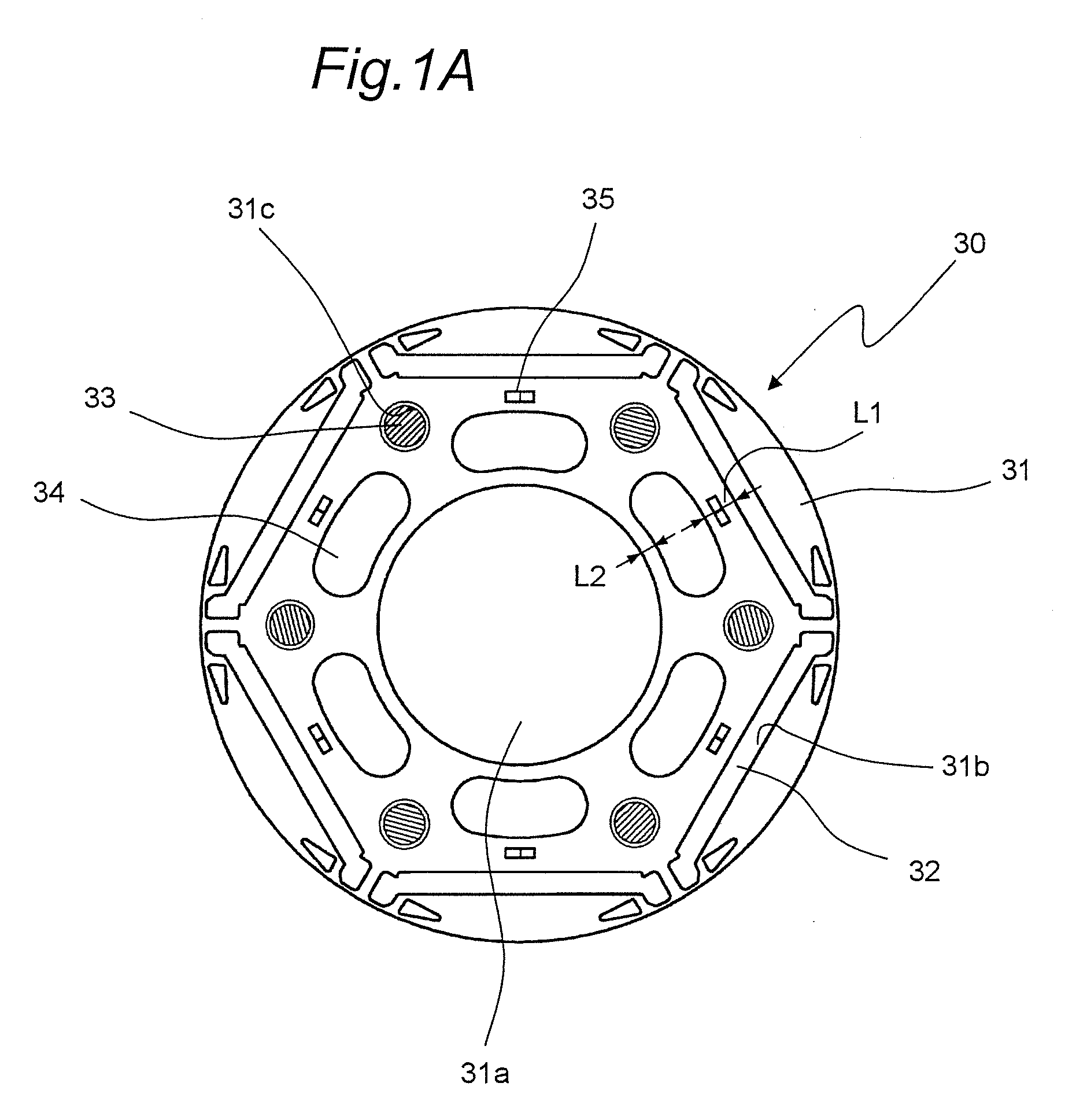
[0035]FIG. 1A shows a top view of a rotor 30 of a motor according to a first embodiment of the invention.

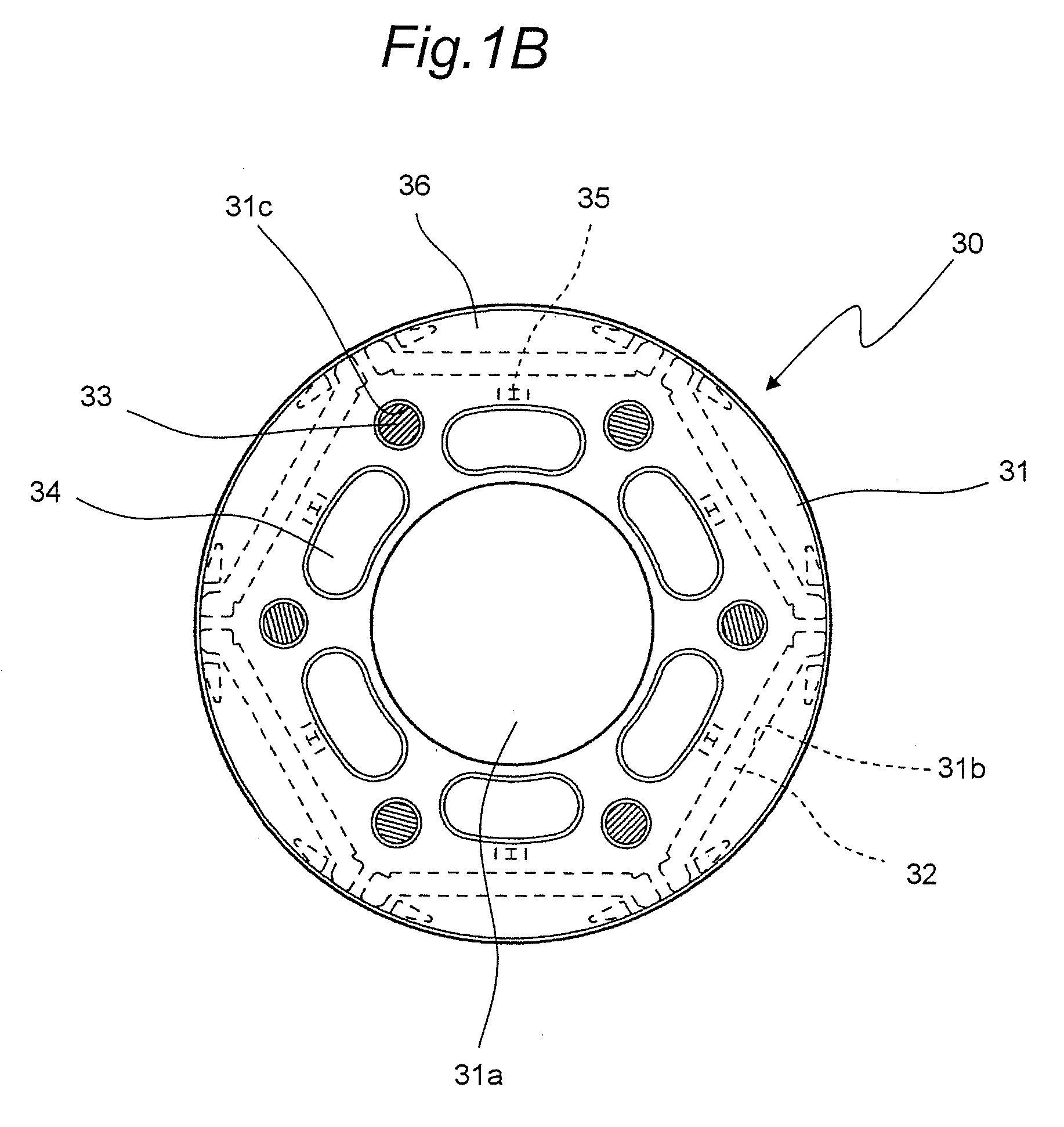
[0036]The rotor 30 of this motor, as shown in FIG. 1A, includes: a rotor core 31 formed of layered electromagnetic steel sheets; six permanent magnets 32 which are embedded respectively in embedding holes 31b formed through the rotor core 31 along an axial direction and which are placed in a generally regular hexagonal shape along a circumferential direction; six holes 31c which are provided near and radially inside vertices of the regular hexagon formed by the permanent magnets 32 of the rotor core 31 and which are formed through the rotor core 31 in the axial direction; rivets 33 as an example of tightening members which are inserted through the six holes 31c, respectively, to tighten the rotor core 31; and through holes 34 as an example of fluid passages which are provided between the rivets 33 of the rotor core 31 so as to be formed through the rotor core 31 in the axial dire...

Example

Second Embodiment

[0049]FIG. 3 shows a top view of a rotor 130 of a motor according to a second embodiment of the invention. The rotor 130 of the motor in this second embodiment is similar, except rivets, to the rotor 30 of the motor of the first embodiment. Therefore, like components are designated by like reference numerals and their description is omitted.

[0050]In the rotor 130 of this motor, as shown in FIG. 3, rivets 33 as an example of tightening members are inserted through every other one out of six holes 31c. The rotor core 31 is tightened by three rivets 33 with layered steel sheets of the rotor core 31 sandwiched from axial both sides by using the end plates 36. Then, the remaining three holes 31c with no rivets 33 inserted therethrough are utilized as fluid passages. It is to be noted that the holes 31c for the rivets 33, if too small, would make it impossible to insert the rivets 33 therethrough, and if too large, would cause decrease in frictional force at end portions ...

Example

Third Embodiment

[0052]FIG. 4 shows a top view of a rotor 230 of a motor according to a third embodiment of the invention. The rotor 230 of the motor in this third embodiment is similar, except rivets and end plates, to the rotor 30 of the motor of the first embodiment. Therefore, like components are designated by like reference numerals and their description is omitted.

[0053]In the rotor 230 of this motor, as shown in FIG.

[0054]3, rivets 33 as an example of tightening members are inserted through every other one out of six holes 31c. The rotor core 31 is tightened by three rivets 33 with layered steel sheets of the rotor core 31 sandwiched from axial both sides by using end plates 37. Then, the remaining three holes 31c with no rivets 33 inserted therethrough are blocked by the end plates 37. It is to be noted that the holes 31c for the rivets 33, if too small, would make it impossible to insert the rivets 33 therethrough, and if too large, would cause decreases in frictional force ...


PUM


Abstract

A motor includes a rotor and a stator surrounding an outer circumferential side of the rotor. The rotor includes a rotor core, a plurality of magnets, a plurality of holes, a plurality of tightening members and a plurality of fluid passages. The rotor core has layered electromagnetic steel sheets with the magnets embedded in the rotor core along an axial direction and placed in a generally regular polygonal shape along a circumferential direction. The holes are formed axially through the rotor core. The holes are arranged radially inside vertices of the generally regular polygon shape formed by the magnets adjacent the vertices. The tightening members are inserted through at least parts of the holes to tighten the rotor core. The fluid passages are disposed between the holes of the rotor core and extend axially through the rotor core.

Description

TECHNICAL FIELD[0001]The present invention relates to a motor of an inner rotor type and a compressor using the motor.BACKGROUND ART[0002]As a first motor, there has conventionally been provided an inner rotor type one including a rotor 330 shown in FIG. 5. The rotor 330 of this motor, as shown in FIG. 5, has a rotor core 331 formed of layered steel sheets, and six permanent magnets 332 embedded in holes formed through the rotor core 331 along its axial direction. In FIG. 5, denoted by reference numeral 335 are caulkings provided in the rotor core 331. The six permanent magnets 332 are arrayed in a regular hexagonal shape along a circumferential direction. Near and radially inside vertices of the regular hexagon formed by the permanent magnets 332, rivets 333 are set through the rotor core 331 so that the layered steel sheets of the rotor core 331 are fixedly sandwiched from axial both sides by end plates (not shown). Then, holes 334 whose cross-sectional shape is curved along the c...

Claims


Application Information

Patent Timeline
IPC IPC(8): F04B17/03H02K1/18H02K1/20
CPCF04C23/008F04C29/0085H02K7/14H02K1/32H02K1/276F04C29/00H02K1/27
Inventor KOJIMA, HIROAKI
Owner DAIKIN IND LTD
Why Eureka
Try Eureka