Optical disc reproducing device and optical disc reproducing method

Inactive Publication Date: 2005-12-01
KK TOSHIBA
View PDF6 Cites 0 Cited by
  • Summary
  • Abstract
  • Description
  • Claims
  • Application Information

AI Technical Summary

Benefits of technology

[0009] As the countermeasures against this, it is considered to change the aperture of the aperture diaphragm in accordance with the CD and the DVD and make the numerical aperture NA for the CD smaller than the numerical aperture NA for the DVD. In doing so, the spot diameter of the laser light on the CD becomes large, and the allowable range for the variation of the optical disc can be widened.
[0013] As the aperture diaphragm of the optical disc, the aperture diaphragm, in which the aperture differs for the first and the second wavelengths, and the aperture in the radial direction of the optical disc is smaller than the aperture in the circumferential direction at the second wavelength, is used. By making the aperture in the radial direction smaller than in the circumferential direction, a spot diameter of a beam in the radial direction is made large, and the influence on a tracking error signal and the like due to variation in the optical disc in the perpendicular direction to a track can be reduced. By making the aperture in the radial direction larger than the aperture in the tangential direction, reduction in the area of the aperture, which ultimately leads to reduction in the optical coupling efficiency, can be suppressed.

Problems solved by technology

Therefore, it is difficult to ensure the performances in both the CD and DVD.
For example, when the optical system is designed not to degrade the performance in the DVD, this optical system becomes too high in the optical magnifying power for CD.
However, reduction in the numerical aperture NA means increase in the loss of light, and causes the reduction in the optical coupling efficiency.

Method used


Image

  • Optical disc reproducing device and optical disc reproducing method
  • Optical disc reproducing device and optical disc reproducing method
  • Optical disc reproducing device and optical disc reproducing method

Examples


Embodiment Construction

[0021] Hereinafter, an embodiment of the present invention will be described in detail with reference to the drawings.

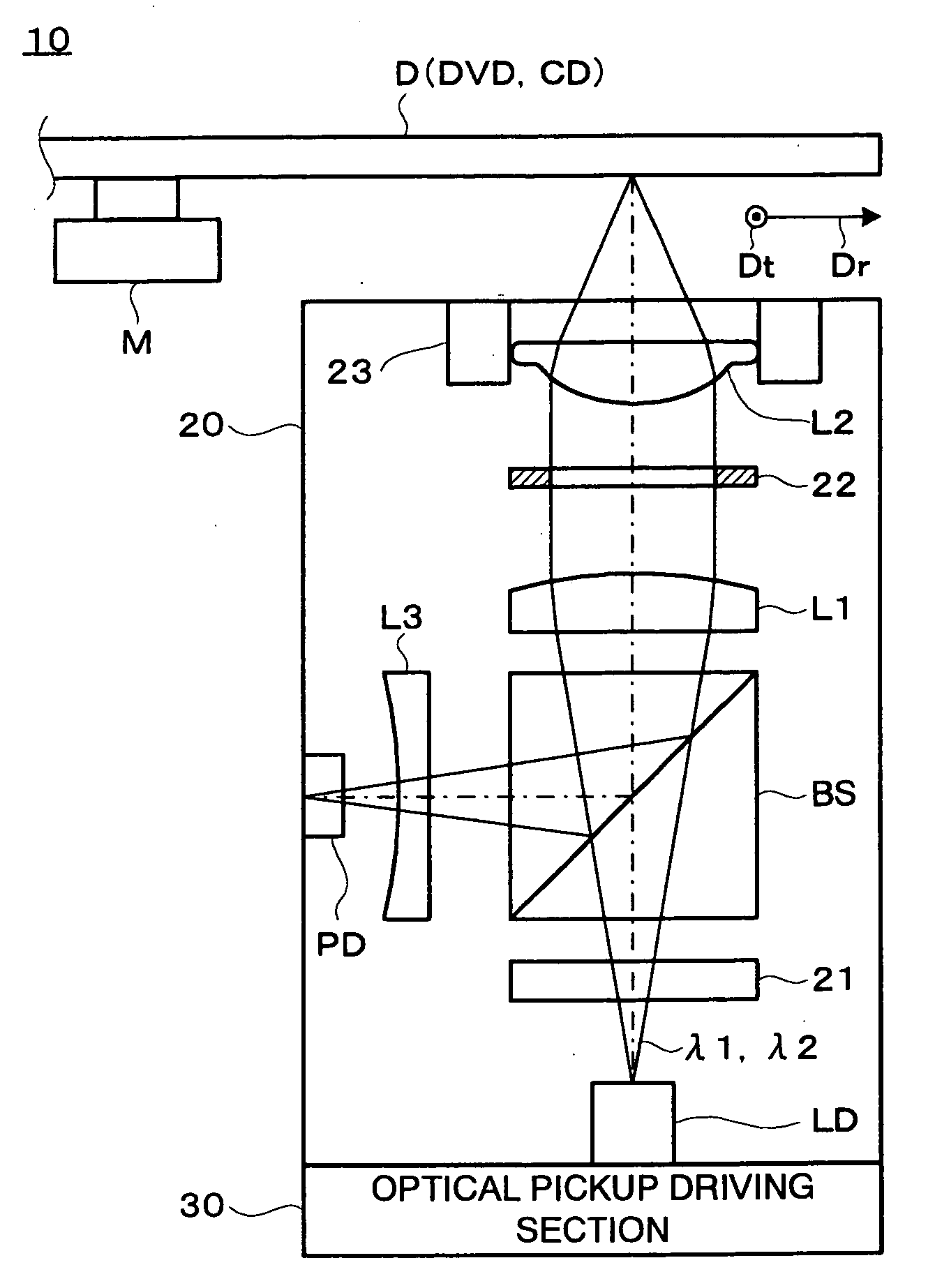
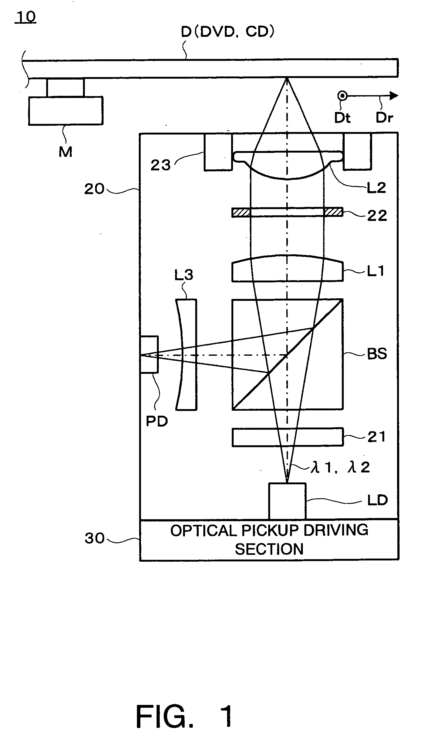
[0022]FIG. 1 is a schematic view showing an optical disc reproducing device 10 according to one embodiment of the present invention.

[0023] The optical disc reproducing device 10 includes an optical pickup 20 and an optical pickup driving section 30, and reads information from plural optical discs D (DVD (Digital Versatile Disc), CD (Compact Disc) and the like) of different specifications.

[0024] The optical disc D is rotated by a disc motor M. This is for the purpose of recording and reproducing the information along a track of the optical disc D.

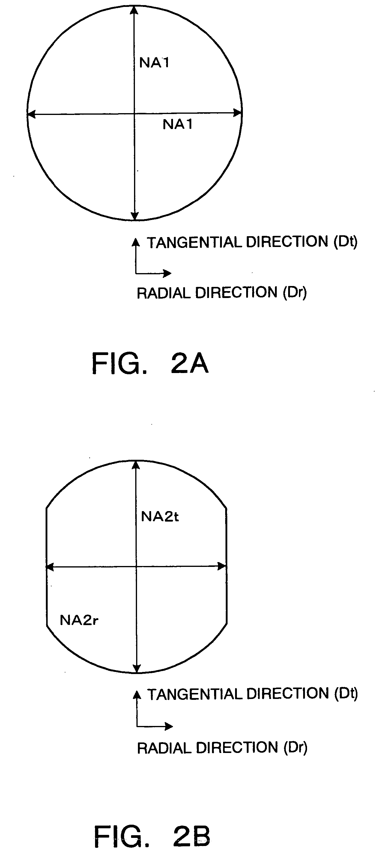
[0025] The optical disc D has a concentric or a spiral track, and information is recorded and reproduced on this track. The direction approximately perpendicular to the track is a radial direction Dr of the optical disc D, and the tangential direction of the track is a tangential direction (circumferential direction) Dt o...


PUM


Abstract

As an aperture diaphragm of an optical disc, the aperture diaphragm in which an aperture differs for a first and a second wavelength, and the aperture in a radial direction of the optical disc at the second wavelength is smaller than the aperture in a circumferential direction is used. By making the aperture in the radial direction small, a spot diameter of a beam is made larger, and thereby influence on a tracking error signal and the like due to variation in the optical disc in a perpendicular direction to a track is reduced. By making the aperture in the radial direction larger than the aperture in a tangential direction, reduction in an area of the aperture, in its turn, in the optical coupling efficiency can be restrained.

Description

CROSS-REFERENCE TO THE INVENTION [0001] This application is based upon and claims the benefit of priority from the prior Japanese Patent Application No. 2004-162617, filed on Mar. 31, 2004; the entire contents of which are incorporated herein by reference. BACKGROUND OF THE INVENTION [0002] 1. Field of the Invention [0003] This invention relates to an optical disc reproducing device and an optical disc reproducing method. [0004] 2. Description of the Related Art [0005] In optical disc reproducing devices, there are the ones including a light source which emits light of plural wavelengths to make it possible to reproduce plural kinds of optical discs (optical recording media) such as a CD (Compact Disc) and a DVD (Digital Versatile Disc). [0006] Here, an art of recording and reproducing different kinds of optical discs by using a two-wavelength semiconductor laser which emits laser light of different wavelengths from two light emitting points is opened to public (see Japanese Patent ...

Claims


Application Information

Patent Timeline
IPC IPC(8): G11B7/135G11B7/00G11B7/125
CPCG11B7/1275G11B2007/13727G11B2007/0006G11B7/139
Inventor YAMAMOTO, TAKAHIRO
Owner KK TOSHIBA
Why Eureka
Try Eureka