Method for producing electronic part package

Active Publication Date: 2010-03-11
SHINKO ELECTRIC IND CO LTD
View PDF2 Cites 15 Cited by
  • Summary
  • Abstract
  • Description
  • Claims
  • Application Information

AI Technical Summary

Benefits of technology

[0052]Further, in the present invention, the recessed part with the size into which the electronic part can be inserted and positioned is formed directly on the support plate or on the first resin layer formed on the support plate. Therefore, the electrode terminals of th

Problems solved by technology

Therefore, the obtained electronic part package

Method used


Image

  • Method for producing electronic part package
  • Method for producing electronic part package
  • Method for producing electronic part package

Examples


Example

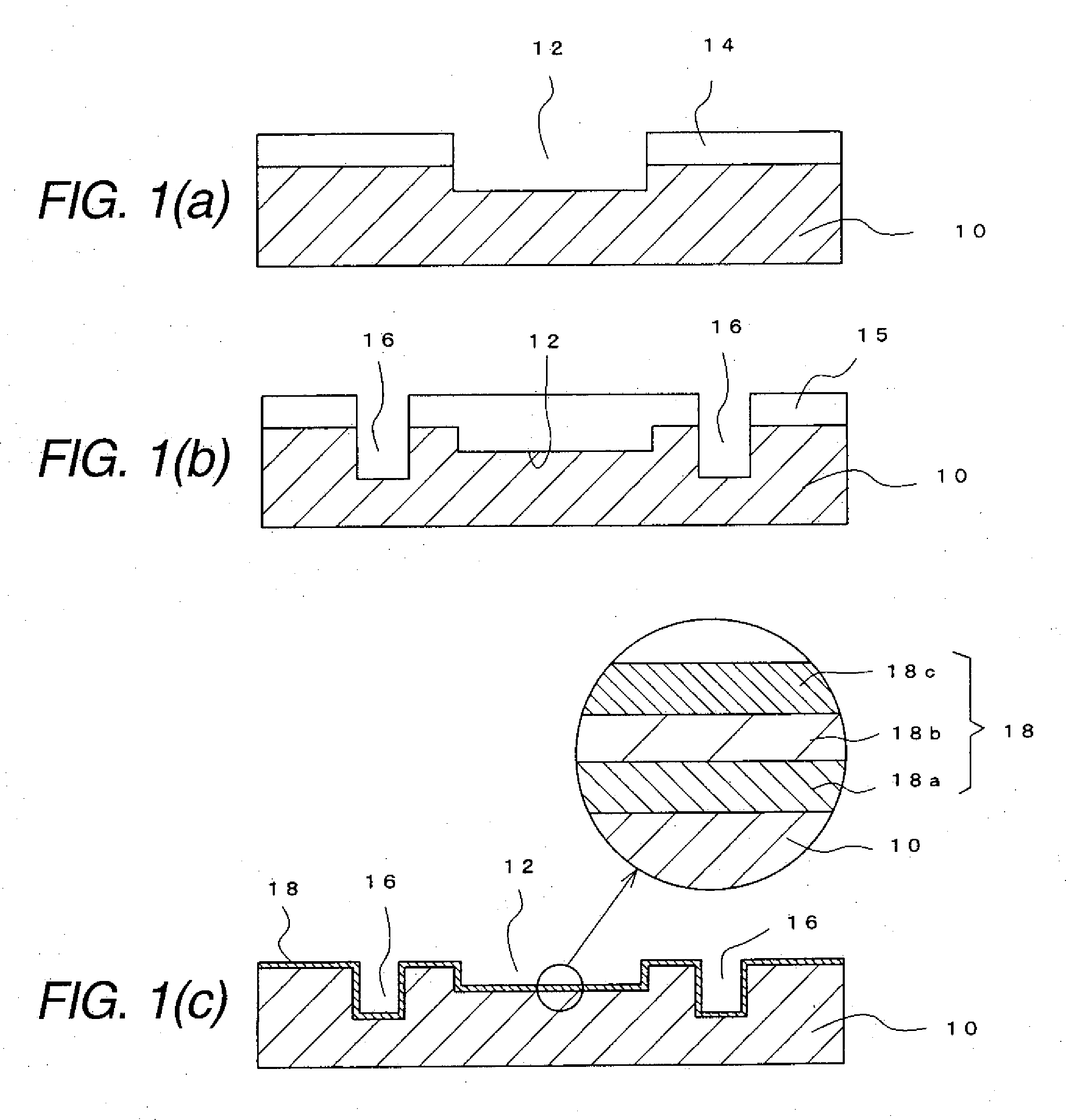
[0062]One example of a method for producing an electronic part package according to the present invention is shown in FIGS. 1 to 3. In the method for producing the electronic part package, as shown in FIG. 1(a), on one surface side of a support plate 10 made of silicon or glass, a recessed part 12 for an electronic part (refer it to as a recessed part 12, hereinafter) is formed that has a size into which a semiconductor element as the electronic part is inserted and positioned and a thickness equal to the thickness of the inserted semiconductor element. The recessed part 12 is formed by forming an opening part in which the one surface side of the support plate 10 is exposed at a prescribed position of a dry film 14 stuck to the one surface side of the support plate 10, and then applying a sandblasting process. According to the sandblasting process, the recessed part 12 can be accurately formed to meet the form of the inserted semiconductor element.

[0063]Further, as shown in FIG. 1(b...


PUM


Abstract

A peeling off layer 18 is formed on an entire surface of one surface side of a support plate 10 including the inner wall surfaces respectively of a recessed part 12 for an electronic part and recessed parts 16 for posts in which the posts 20 are formed. Then, the recessed parts 16 are filled with metal to form the posts 20. Then, conductor patterns 28 are formed that electrically connect the electrode terminals 22a of the electronic part 22 inserted into the recessed part 12 to the posts 20. Then, an insulating layer covering the conductor patterns 28 is formed to form an electronic part package 30 on the one surface side of the support plate 10 through the peeling off layer 18. After that, the electronic part package 30 is separated from the support plate 10 by the peeling off layer 18.

Description

CROSS-REFERENCE TO RELATED APPLICATIONS[0001]This application is based on and claims priority under 35 U.S.C. §119 from Japanese Patent Application No. 2008-228204 filed on Sep. 5, 2009.BACKGROUND OF THE INVENTION[0002]1. Technical Field[0003]The present invention relates to a method for producing an electronic part package, and more particularly to a method for producing an electronic part package in which electrode terminals of a mounted electronic part are electrically connected to posts as external connecting terminals by electrically conductive patterns.[0004]2. Related Art[0005]An electronic part such as a semiconductor element has been progressively thinned in order to miniaturize a mounting device on which the electronic part is mounted. Accordingly, as for an electronic part package on which the electronic part is mounted, the thin electronic part package has been requested similarly to the electronic part mounted thereon.[0006]To meet such a demand, U.S. Pat. No. 6,586,822...

Claims


Application Information

Patent Timeline
IPC IPC(8): H01L21/50
CPCH01L21/568H01L21/6835H01L2224/73204H01L2224/32225H01L2224/16225H01L2924/01033H01L2924/01024H01L2924/01006H01L2924/01005H01L2924/19041H01L2924/1532H01L2924/15311H01L2924/15165H01L2924/15153H01L23/3107H01L23/5389H01L24/24H01L24/82H01L25/0657H01L2221/68345H01L2224/24226H01L2224/24227H01L2224/82001H01L2225/06517H01L2225/0652H01L2225/06572H01L2924/01015H01L2924/01029H01L2924/01078H01L2924/09701H01L2924/00H01L2924/18162H01L2224/04105
Inventor SAKAGUCHI, HIDEAKISUNOHARA, MASAHIROHIGASHI, MITSUTOSHI
Owner SHINKO ELECTRIC IND CO LTD
Why Eureka
Try Eureka