Wireless lock

a technology of wireless locks and wires, applied in the direction of wireless communication, eavesdropping prevention circuits, instruments, etc., can solve the problems of large amounts of information, unauthorized persons getting hold of operational devices, and not protecting devices

Inactive Publication Date: 2010-03-11
TELEFON AB LM ERICSSON (PUBL)
View PDF4 Cites 34 Cited by
  • Summary
  • Abstract
  • Description
  • Claims
  • Application Information

AI Technical Summary

Benefits of technology

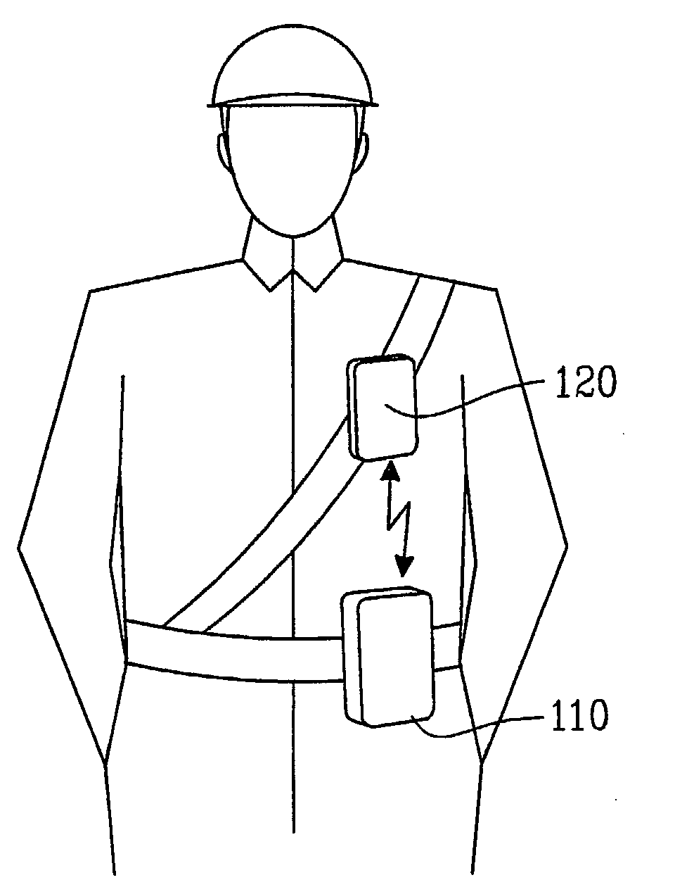
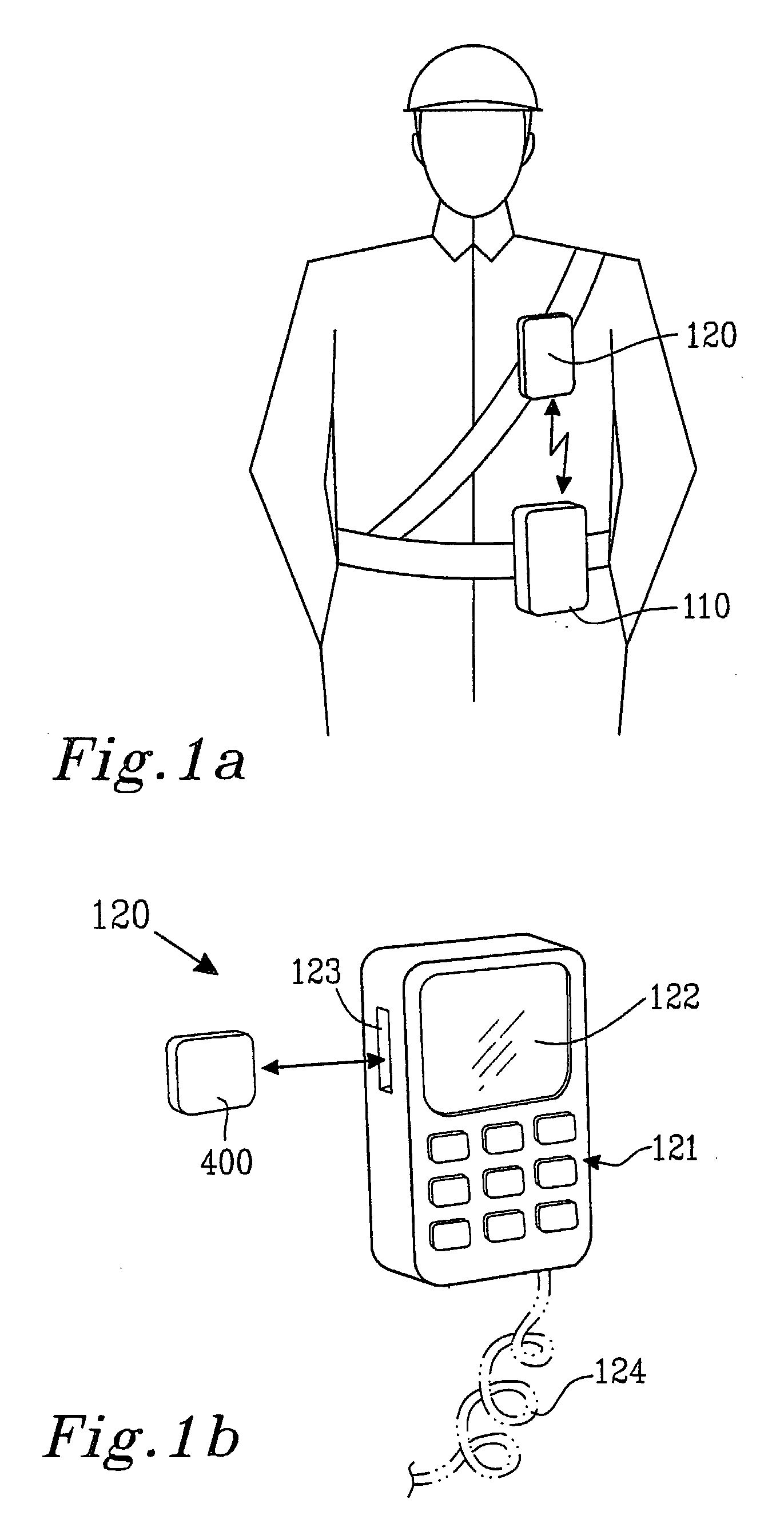
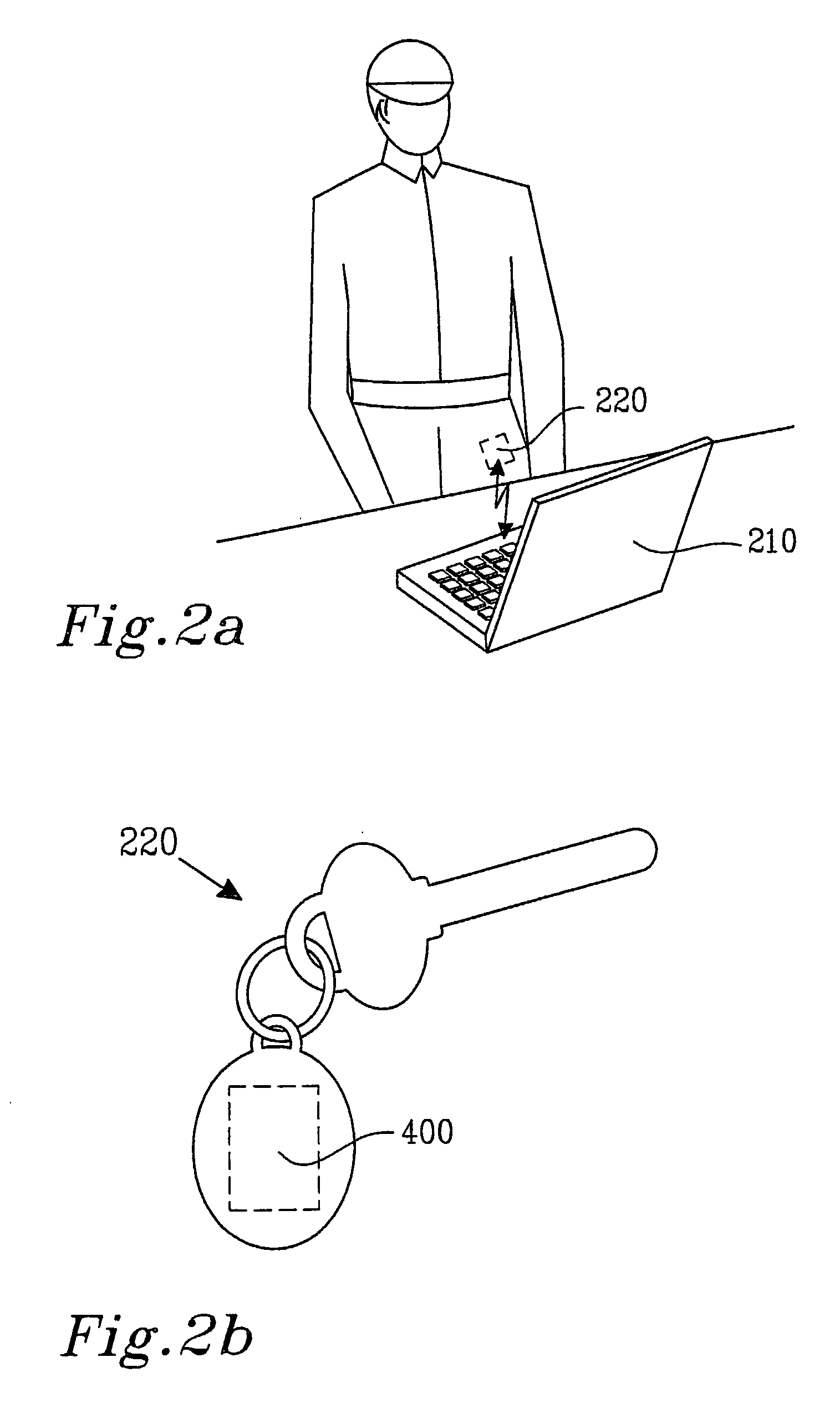
[0010]Consequently, it should be clear that a first device and a second device in a protection system according to the present invention can be arranged so that the devices have to be located within a short distance from each other if access to the contents in both devices should remain enabled. In other words, access to the contents in both devices is disabled if the devices are located too far away from each other.

Problems solved by technology

Such powerful devices are often carrying large amounts of information that has to be protected from access by unauthorized persons.
However, a PIN-code or a password that is entered during start-up does not protect the device once it has become operational.
Consequently, there is a risk that an unauthorized person gets hold of an operational device and consequently the information and / or the application(s) therein.
Hence, a time-out function has the obvious drawback that the device may not yet have been locked when it is accessed by an unauthorized person.
In addition, using a PIN-code or similar is not practical or even recommended in all situations.
For one thing, entering a PIN-code each time a locked device is to be used can be a source of irritation.
More importantly, in some situations entering a PIN-code may cause a serious and harmful delay and it may even be impossible, especially in connection with information-carrier devices used by policemen, firefighters or ambulance personnel or similar.
Such personnel are frequently involved in stressful and demanding situations that require measures without delay, and / or where the required measure occupies the hands of the personnel.

Method used


Image

  • Wireless lock
  • Wireless lock
  • Wireless lock

Examples


first embodiment

A First Embodiment

[0047]The flowcharts in FIG. 5-6 illustrate how the exemplifying system 300 in FIG. 3 can be operated according to a first embodiment of the present invention.

[0048]According to a first step 510 in the flowchart of FIG. 5 the security-unit 400 in the information-carrier device 310 is disabling access to the information and / or application(s) in the carrier device 310. A disabling signal may e.g. be provided from the controller 410 via the output connection 415 to the information-storing unit(s) 315 and / or application(s) in the carrier device 310.

[0049]According to a second step 520 in the flowchart of FIG. 5 the security-unit 400 in the information-carrier device 310 is preferably transmitting an intermittent wireless request-signal, i.e. transmitting a request-signal during predetermined intervals. In general, transmitting or receiving is preferably achieved by the controller 410 commanding the transceiver 420 to transmit or receive.

[0050]A timer is then initiated ...

second embodiment

A Second Embodiment

[0064]The flowcharts in FIG. 7-8 show how the exemplifying system 300 in FIG. 3 can be operated according to a second embodiment of the present invention.

[0065]According to a first step 710 in the flowchart of FIG. 7 the security-unit 400 in the information-carrier device 310 is disabling access to the information and / or application(s) in the carrier device 310 in a similar or identical way as previously described in connection with step 510 in FIG. 5.

[0066]A timer is then initiated and started in a second step 720 in a similar or identical way as previously described in connection with step 520 in FIG. 5.

[0067]The initiation and start of the timer in step 720 is then followed by a third step 730 wherein the controller 410 commands the transceiver 420 to receive a possible enabling signal. If a signal is received it will be converted by the transceiver 420 and supplied to the controller 410 via the input connector 412. The controller 410 then processes the receive...


PUM


Abstract

The invention provides for a portable device, a system comprising at least two portable devices and a method according to which at least a first portable device and at least a second portable device can be arranged so that said devices have to be located within a short distance from each other if access to the contents in said first device should remain enabled and / or access to the contents in said second device should remain enabled.

Description

FIELD OF THE INVENTION[0001]The present invention relates to an automatic protection system and to a method of using such a system. In particular, the invention relates to an automatic information protection system having a wireless information-carrier device equipped with an enabling / disabling control function, and a wireless control device for performing wireless communication with said wireless information-carrier device, for performing enabling and disabling functions automatically, and method of use thereof.BACKGROUND OF THE INVENTION[0002]Over a period of time there has been continuous development of powerful portable devices. A non exhaustive list of such portable devices are laptops, personal digital assistants (PDA:s), digital notebooks, mobile phones and even land-radios (e.g. walkie-talkies) etc. Such powerful devices are often carrying large amounts of information that has to be protected from access by unauthorized persons. These powerful devices may also comprise compu...

Claims


Application Information

Patent Timeline
Patent Type & Authority Applications(United States)
IPC IPC(8): H04M3/16
CPCG06F21/35G06F21/74G06F2221/2103G06F2221/2105H04W12/08G06F2221/2129G06F2221/2147H04L63/0492H04L63/0853G06F2221/2111H04W12/63H04W12/33
Inventor JONSSON, MATTIAS
Owner TELEFON AB LM ERICSSON (PUBL)
Why Eureka
Try Eureka