Device and control procedure for recovery of kinetic energy in railway systems

a technology of kinetic energy recovery and control procedure, which is applied in the direction of trolley lines, position/direction control, dc motor stoppers, etc., can solve the problems of low efficiency of total available energy that could be injected in the grid and the voltage fluctuations produced in other systems, and achieve the effect of improving the wave quality of curren

Active Publication Date: 2010-03-11
INGETEAM POWER TECH
View PDF10 Cites 29 Cited by
  • Summary
  • Abstract
  • Description
  • Claims
  • Application Information

AI Technical Summary

Benefits of technology

[0028]The device of the invention can also fulfil other functions. Thus, in the AC side the device of the invention can operate as an active filter and improve the wave quality of the current consumed by the diode bridge, or compensate the reactive power to obtain a cos(phi) value approaching 1.

Problems solved by technology

This is done overcoming drawbacks of the state of the art such as the low efficiency with respect to the total available energy that could be injected in the grid and the voltage fluctuations produced in other systems.

Method used


Image

  • Device and control procedure for recovery of kinetic energy in railway systems
  • Device and control procedure for recovery of kinetic energy in railway systems
  • Device and control procedure for recovery of kinetic energy in railway systems

Examples


second embodiment

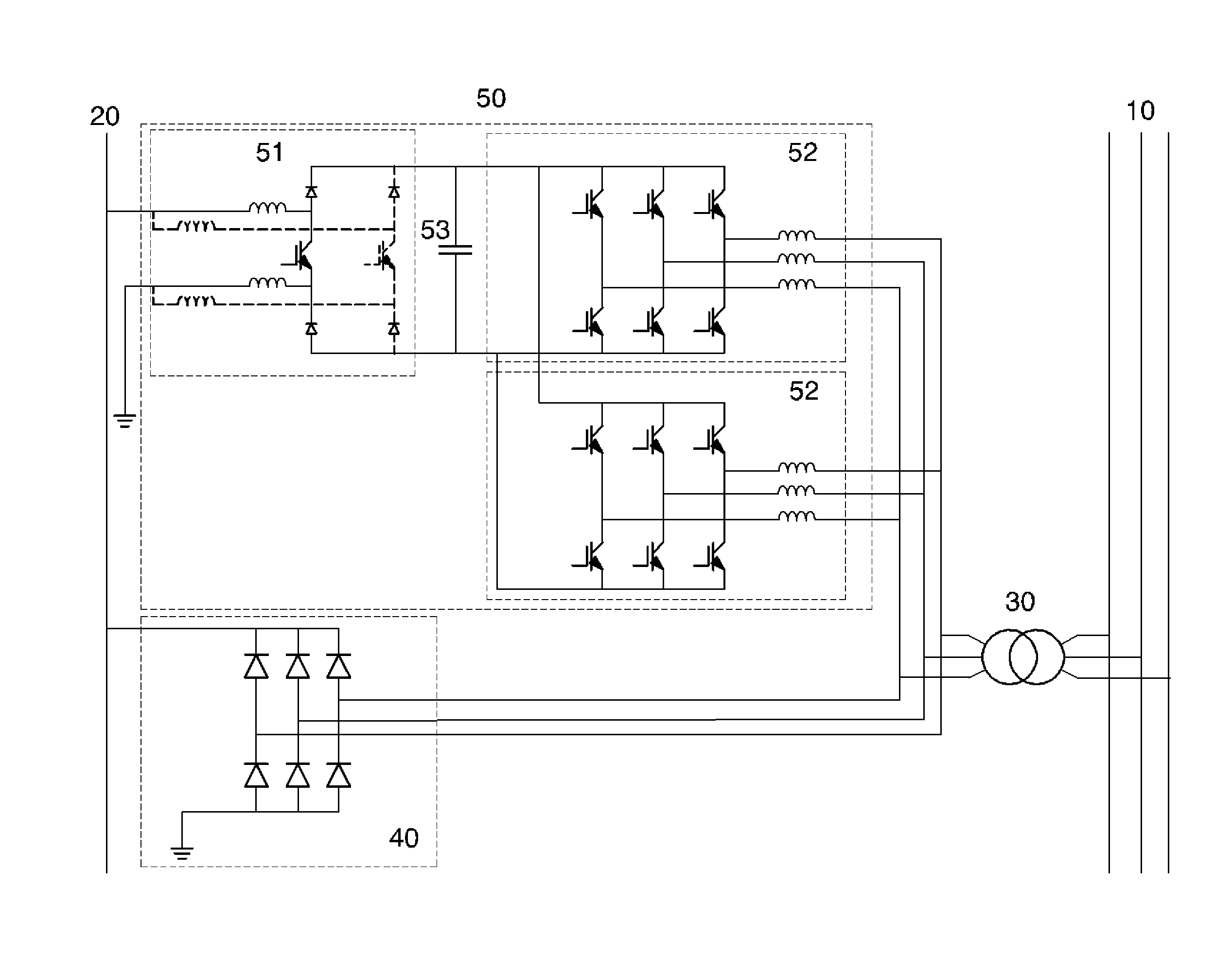
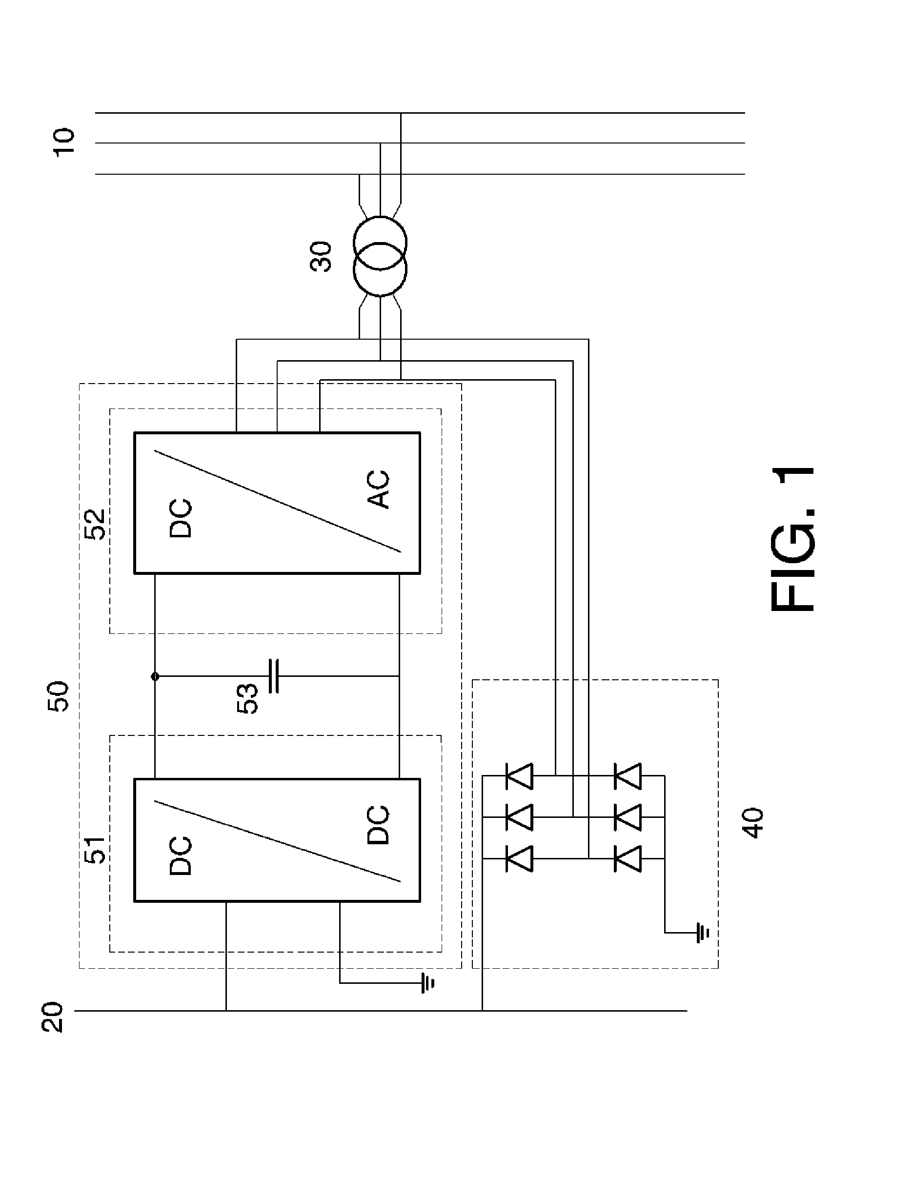
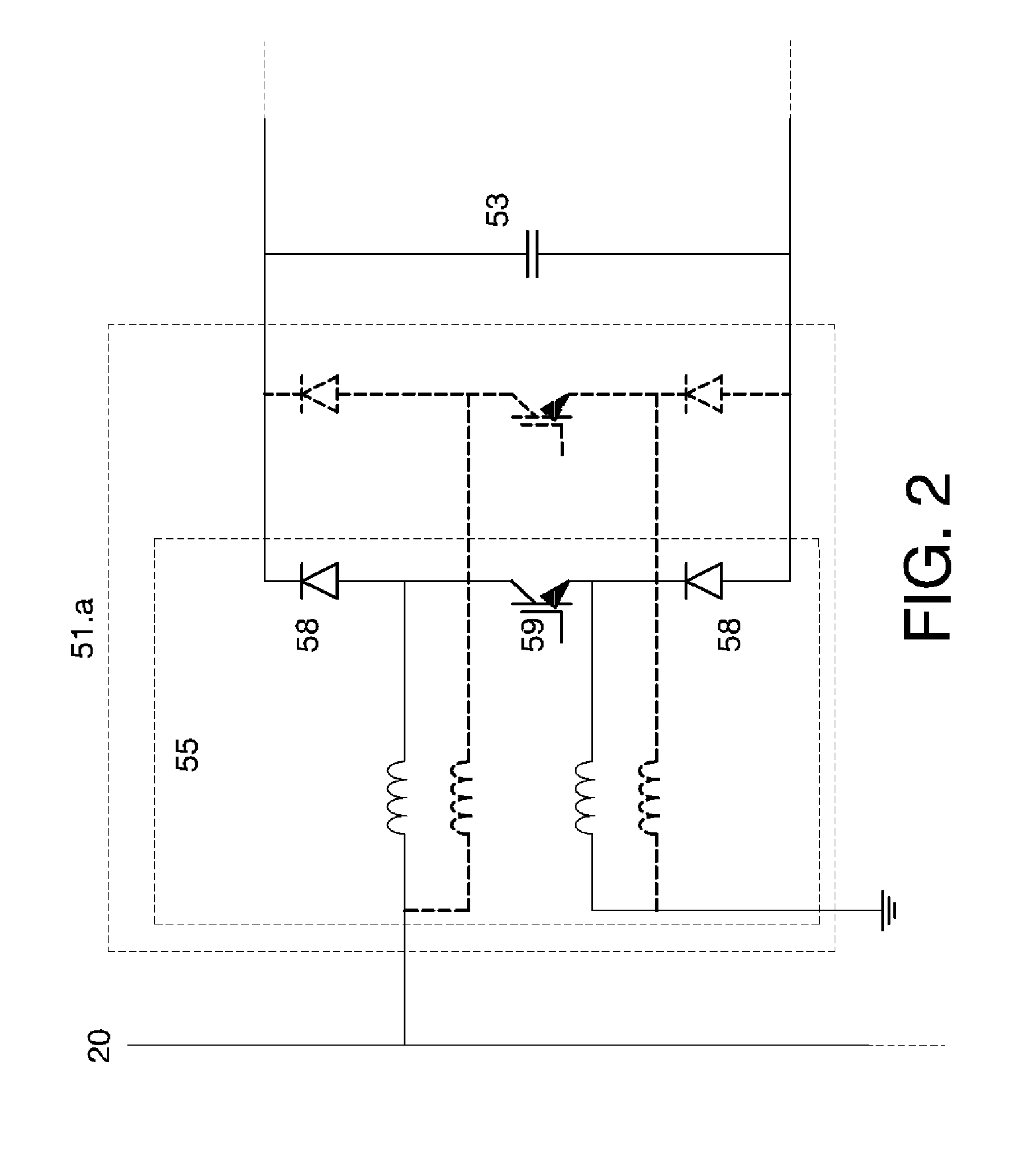
[0011]In the aforementioned first block, it is formed by two branches with at least two semi-conducting switches in each one, so that the mid point of one of the branches is connected through a coil to the positive terminal of the catenary and the mid point of the other branch is connected through another coil to the ground or negative terminal of the catenary.

[0012]In one embodiment of these two branches the upper semi-conducting switch of the branch associated to the positive terminal of the catenary and the lower semi-conducting switch of the branch associated to the negative terminal of the catenary are current-unidirectional switches of the diode type, while the other two semi-conducting switches are current-bidirectional switches of the IGBT type.

[0013]In another embodiment of these two branches the aforementioned semi-conducting switches of each of the two branches are current-bidirectional switches of the IGBT type.

third embodiment

[0014]In the aforementioned first block of the device, this first block is formed by at least one branch with at least four semi-conducting switches wherein at least the two middle switches can be controlled in startup and shutdown, and the mid point formed between the two upper semi-conducting switches is connected through a coil to the negative terminal of the catenary.

[0015]In this third embodiment of the first block, both the upper and lower semi-conducting switches of the said branch can be current-unidirectional switches of the diode type and both middle semi-conducting switches can be current-bidirectional switches of the IGBT type, in addition providing that in the said third embodiment of the first block the four semi-conducting switches in the aforementioned branch are current bidirectional switches of the IGBT type.

first embodiment

[0016]In the said second block of the device of the invention, this second block is formed by three branches with at least two current-bidirectional semi-conducting switches in each branch, so that each branch corresponds to one phase of the three-phase voltage system of the three-phase grid and optionally includes an inductance connected between the mid point of the branch and the corresponding phase of the transformer; it is possible to do without said inductances if the corresponding leak inductance of the transformer is enough to ensure current regulation.

[0017]In a second embodiment of said second block of the device, conceived for high-voltage applications, a three-level NPC circuit is used with current-unidirectional semi-conducting switches of the diode type joined to a mid point of the intermediate bus, which limit the voltage supported by other semi-conducting switches of the IGBT type, in this case the intermediate bus having two capacitors between which the aforementione...


PUM


Abstract

The railway system has a DC voltage catenary (20) connected to a rectifier bridge block (40) that is in turn connected to a transformer (30) joined to a three-phase AC grid (10). The device (50) has a first DC/DC voltage raising block (51) connected between the catenary (20) and an intermediate bus that is connected to a second DC/AC three-phase current generation block (52) joined to the transformer (30). The first block (51) allows raising the DC voltage of the catenary (20) generating a controlled voltage with which the second block (52) generates a high-quality three-phase current that is delivered to the grid (10).

Description

OBJECT OF THE INVENTION[0001]The present invention, as stated in the title of this descriptive memory, relates to a device and control procedure for recovery of kinetic energy in railway systems, the object of which is to optimize the energy recovery made possible in train braking, allowing to inject in the corresponding electric grid a high-quality three-phase current, even in high grid voltage situations and using the pre-existing transformer in the substation supply connection. The invention produces the regeneration of energy in traction systems during the braking processes of trains associated to a DC catenary so that, with the device of the invention, when the voltage read in the catenary is greater than a specified value, energy is extracted to inject it in the corresponding alternating current grid. This is done overcoming drawbacks of the state of the art such as the low efficiency with respect to the total available energy that could be injected in the grid and the voltage...

Claims


Application Information

Patent Timeline
Patent Type & Authority Applications(United States)
IPC IPC(8): G06F1/28B60M1/12
CPCB60M3/06
Inventor IBAIONDO MADARIAGA, HARKAITZROMO BERGADO, ASIERGONZALEZ NARVAIZA, IKERGARIN IBARZABAL, XABIEROLEA UNAMUNO, FRANCISCO JAVIER
Owner INGETEAM POWER TECH
Why Eureka
Try Eureka