
Magnetic sensing device for navigation and detecting inclination

a magnetic sensing device and navigation technology, applied in the direction of speed measurement using gyroscopic effects, navigation by terrestrial means, instruments, etc., can solve the problems of poor resolution, complicated navigation system, and limited resolution of navigation systems, so as to improve the accuracy of navigation and detection. the effect of detecting the inclination

Active Publication Date: 2010-03-11
MEMSIC
View PDF7 Cites 9 Cited by
  • Summary
  • Abstract
  • Description
  • Claims
  • Application Information

AI Technical Summary

Benefits of technology

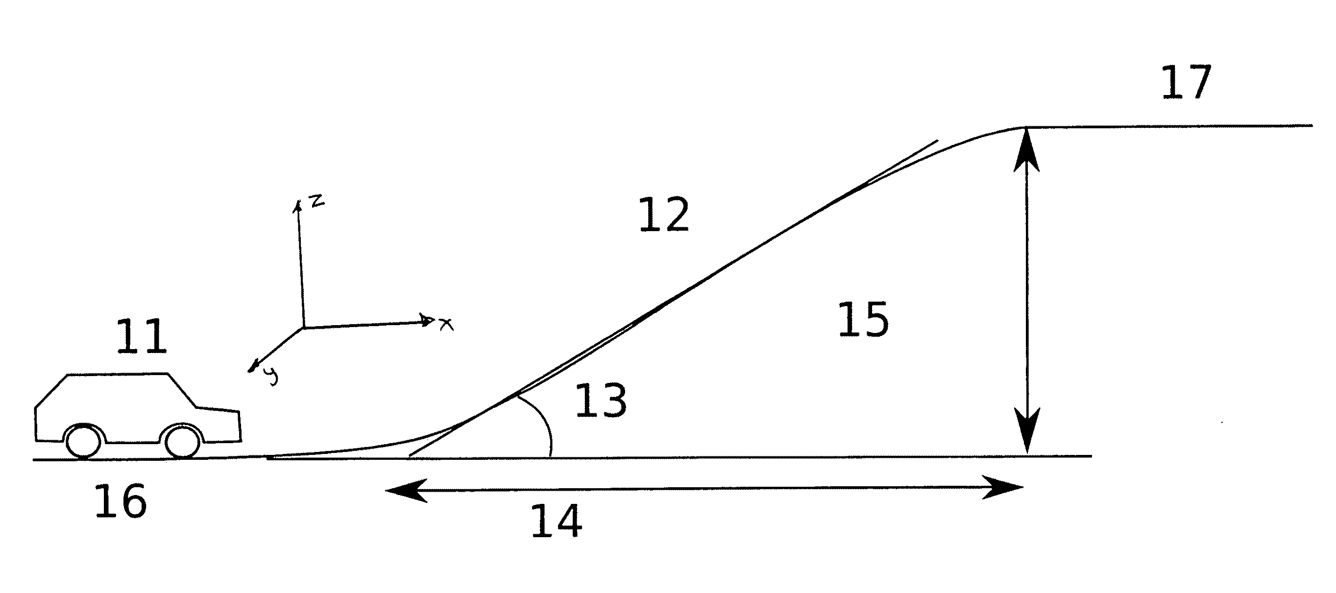
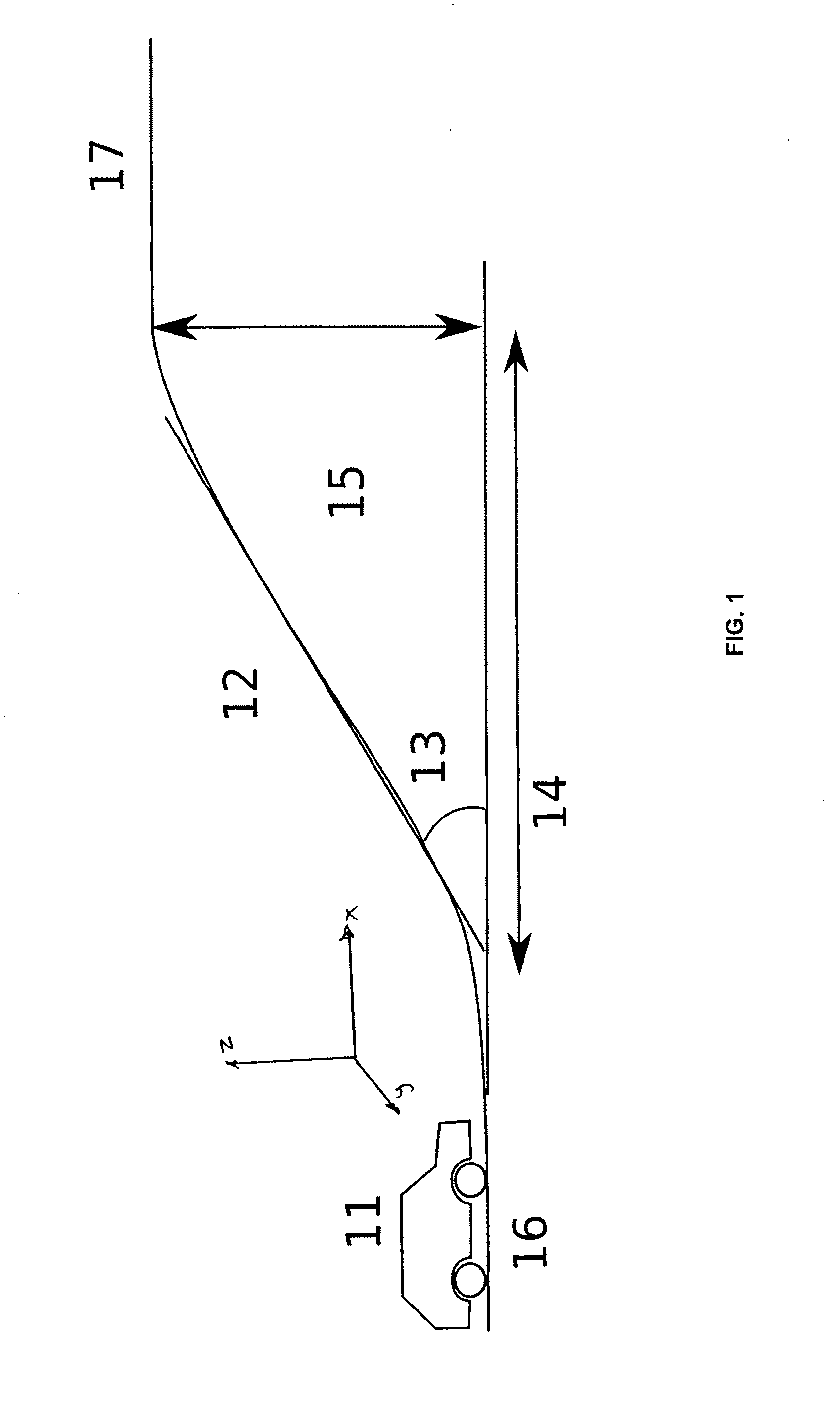
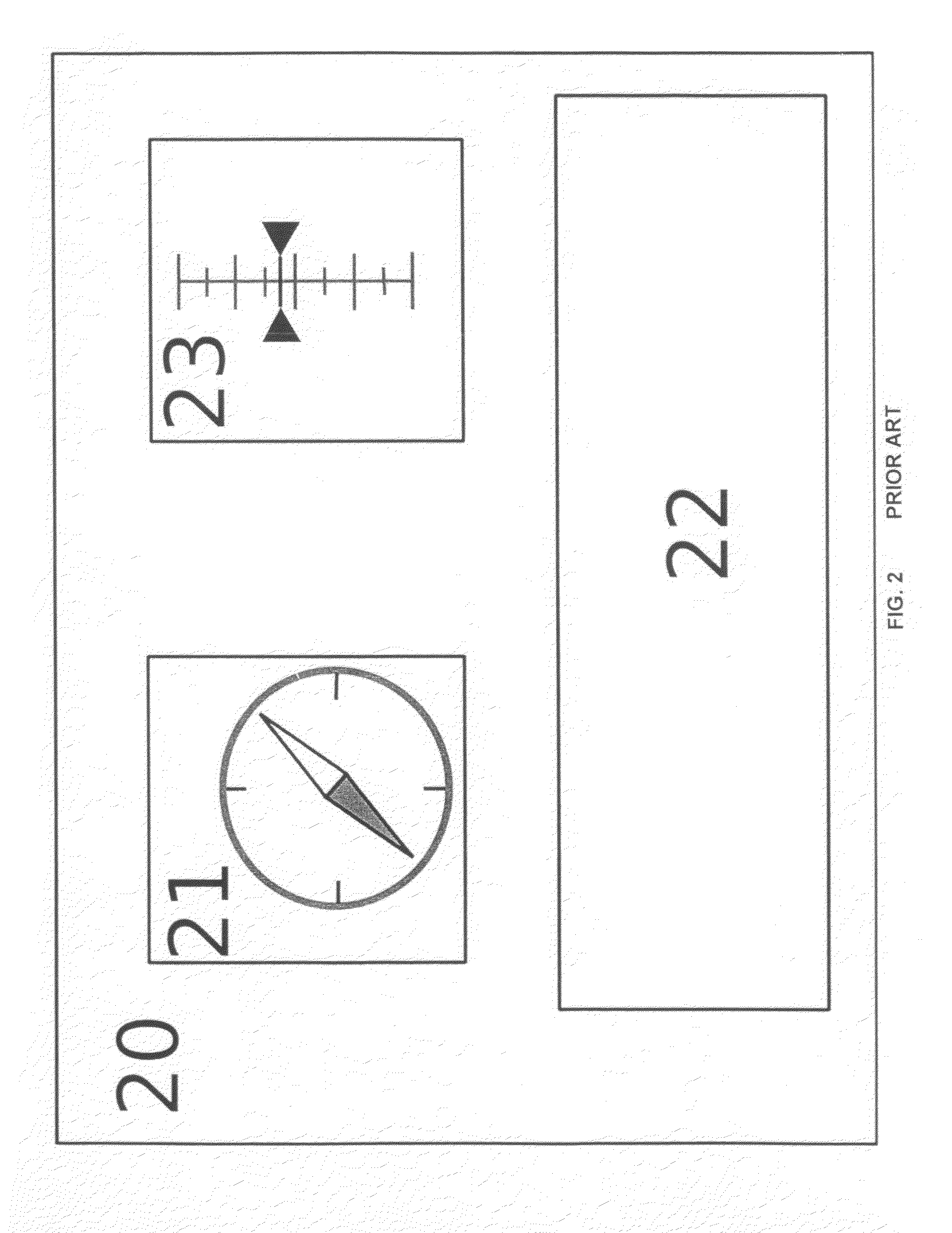
[0012]The invention will be better understood by reference to the following more detailed description and accompanying drawings where like reference numbers refer to like parts:

Problems solved by technology

However, such navigation systems continue to have limited resolution, which displays erroneous data to the vehicle operator or passenger / navigator.
Indeed, although satellite receivers are adapted to provide vertical resolution that is suitable for displaying the location of the vehicle, poor resolution manifests and is further complicated at, for example, complex interchanges having plural overpasses, underpasses, on-ramps, and off-ramps that overlie or underlie each other.
When elevated roadways and viaducts follow the same or substantially the same route of an underlying roadway, it is difficult for the navigational system to differentiate between the two roadways and, moreover, on which of the roadways the vehicle is actually traveling.
Thus, in many cases having short horizontal distances, the navigational system has no way of correctly assessing the vehicle's true position.
Each of these solutions, however, requires additional circuitry, e.g., the addition of an accelerometer and / or of a gyroscope, which creates additional cost and adds to the sophistication of manufacture.
Furthermore, the added circuitry increases the size and power needs of the receiver system to which they are added.
Disadvantageously, with accelerometers, it is difficult to differentiate between acceleration data resulting from natural changes in speed of the vehicle (acceleration, deceleration) and data resulting from a slope.

Method used


Image

  • Magnetic sensing device for navigation and detecting inclination
  • Magnetic sensing device for navigation and detecting inclination
  • Magnetic sensing device for navigation and detecting inclination

Examples


first embodiment

[0034]According to the present invention, if the roll angle (Ω) is zero, the variations of Mx and My with respect to the pitch angle are as follow:

∂Mx∂Φ Ω=0=-sin(Φ)·cos(Θ)Hx+cos(Φ)Hzand∂My∂Φ Ω=0=0.

[0035]Accordingly, by monitoring sensor output, and, more particularly, by focusing on instances at which:

∂Mx∂t≠0;and∂My∂t=0,

it is possible to detect a pitch variation. The sign of Mx and ΔMx can then be used in correlation to determine the positive or negative nature of the variation. Those skilled in the art can appreciate that this method can be further adapted to detect variations of the roll angle (Ω) and the scope of the present invention is not limited to the pitch variation detection.

[0036]When the partial derivative

∂Mx∂Φ Ω=0=0,

depending on the value of the Earth magnetic field angle (φH), there are more possible solutions. Indeed, if the magnetic field angle is less than or equal to 45°, there exists a roll angle (Ω) value that satisfies the equation:

∂Mx∂Φ Ω=0=0.

Notwithstanding, i...

second embodiment

[0037]In the present invention, the amplitude of the magnetic field vector projected on the sensor's plan, Mplan, can be calculated using the equation:

Mplan=Mx2+My2

[0038]Those skilled in the art can appreciate that, although the amplitude of the Earth's magnetic field vector varies, local variations are negligible. Consequently, within an area of several square kilometers, the Earth's magnetic field vector can be considered constant and uniform. Thus, using the rule:

∂Mplan∂t>ΔMplan,treshold

it is possible to detect variations in either the pitch angle (Φ) or the roll angle (Ω). The distinction between those angles as well as the sign of the variation can be determined using the processed yaw value (Θ) and the measured values Mx and My.

[0039]Those skilled in the art can also appreciate that, depending on the details of the implementation, it is possible to replace the partial derivative

∂Mplan∂t

with an equivalent combination of Mplan, Θ, Mx, and My. Hence, the scope of this invention i...

third embodiment

[0040]In the present invention, the sensor 41 is replaced by a three-axis magnetic sensor. Advantageously, adding z-axis magnetic field measurement facilitates the calculation of pitch and roll variations. For example, during a pitch variation, the y-axis output remains constant as long as the roll angle (Ω) is null. Consequently, it is very difficult for a dual axes sensor system to provide correct and precise information about pitch and roll if they occur at the same time.

[0041]Although a two-axis magnetic sensor cannot completely measure the Earth's magnetic field vector, a three-axis magnetic sensor can measure the z-value of the vector. As a result, one can assume that Hx and Hz are known and / or can be acquired and stored.

[0042]As additional information, if the yaw (Θ) is known and is acquired while the vehicle 11 is traveling in a straight line on a plan parallel to the Earth's surface, the z-axis output is governed by the following equation:

Mz=(sin(Ω)sin(Θ)−cos(Ω)sin(Φ)cos(Θ)...


PUM


Abstract

A system and device for detecting yaw and changes in pitch angle for use with navigational and positional devices. The system and device include a multi-axis magnetic field sensing device and a controller. Preferably, the magnetic field sensing device is a multi-axis magnetic compass that is capable of sensing variations in pitch and yaw. The controller is adapted to process yaw and pitch rotational data to determine a positive or a negative change in pitch.

Description

CROSS REFERENCE TO RELATED APPLICATIONS[0001]Not ApplicableSTATEMENT REGARDING FEDERALLY SPONSORED RESEARCH OR DEVELOPMENT[0002]Not ApplicableBACKGROUND OF THE INVENTION[0003]The present invention is related to the field of navigational systems and devices and, more particularly, to satellite-based navigational systems and devices capable of detecting inclination and changes in inclination of an object in motion.[0004]In many areas, on-board, satellite-based, three-dimensional travel navigation systems using, for example, the global positioning system (“GPS”) have improved dramatically over the past few years. However, such navigation systems continue to have limited resolution, which displays erroneous data to the vehicle operator or passenger / navigator. Indeed, although satellite receivers are adapted to provide vertical resolution that is suitable for displaying the location of the vehicle, poor resolution manifests and is further complicated at, for example, complex interchanges...

Claims


Application Information

Patent Timeline
Patent Type & Authority Applications(United States)
IPC IPC(8): G01C9/00
CPCG01C21/26G01C21/08
Inventor LAGOUGE, MATTHIEUMAO, YAOHUI
Owner MEMSIC
Learn More