Dust Prevention And Removal Device

Active Publication Date: 2010-03-18
SC JOHNSON & SON INC
7 Cites 42 Cited by

AI-Extracted Technical Summary

Problems solved by technology

In many household environments, a number of airborne particulates, e.g., allergens, dust and/or other airborne matter are present which can create respiratory problems for individual...

Method used

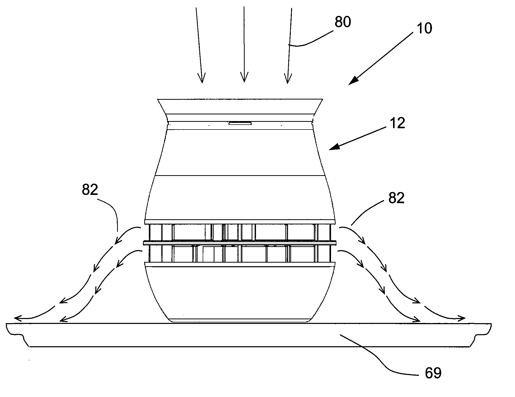
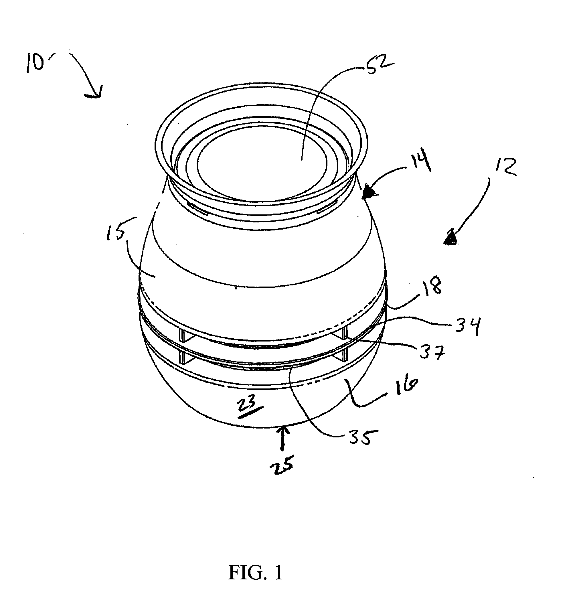
[0060]Outlet grill 18 generally comprises a series of horizontal rungs 34 circumferentially disposed around the outside of housing 12 and defining apertures 35 for airflow therebetween. Rungs 34 are generally supported by a series of spaced struts 37. Struts 37 are preferably configured to minimize the noise and frequency matching with respect to the fan 58 of the present invention. Rungs 34 are positioned such that an operator's or child's fingers are incapable of fitting through into the interior of the housing 12 to touch the fan 58 or electronic components disposed within the device 10 in compliance with UL standards, and specifically, UL 507. Further, grill 18 generally comprises a downwardly facing opening 36 in communication with the interior of housing 12. Grill 18 further includes a projection 38 extending upwardly from upper surface 24 that generally defines a cylindrical shaft 40 having an opening 42 at an upper end thereof.
[0062]Inlet grill 44 is generally configured to support and secure a filter element 52 on an upper surface thereof. Alternatively, inlet grill 44 may be replaced or adapted to work in conjunction with a filter frame (not shown) of the kind known in the art. Filter element 52 can be formed of any suitable material capable of removing dust and other allergens from airflow passing therethrough. Preferably, the filter element 52 comprises a thermoformed nonwoven element. For example, the filter element 52 may comprise a thermoformed filter or the like. The thermoforming of the filter 52 allows for the filter 52 to be shaped in a concave or dome-like shape to allow for increased filter efficiency. Alternatively, the filter may be substantially flat. The filter 52 should also preferably comprise a dust holding capacity of about 600 mg. More preferably, the filter 52 should have a dust holding capacity of about 700 mg and a surface area of approximately 45 square centimeters (7 in.2). The filter element 52 may also comprise a sticky nonwoven filter element, electrostatic filter element or HEPA filter element. Once the filter element 52 becomes clogged with dust and other particles, the filter element 52 may be removed from the housing 12 and replaced with a clean filter element 52.
[0065]In a preferred embodiment of the device 10, filter element 52 further includes a lock and key system (not shown) either disposed on the filter element 52 itself or, alternatively, on a filter frame thereof. In one preferred embodiment of the present invention, the filter frame (not shown) of filter element 52 or similar support structure includes a projection (not shown) configured to activate a switch within the device 10 of the present invention. Preferably, the projection comprises an injection molded plastic part disposed on the filter frame. Alternatively, the filter element 52 may itself include a button or thumbtack (not shown) disposed on a surface thereof for engaging the switch within device 10. In operation, device 10 will not operate unless it is fitted with a filter element 52 compatible therewith. The present embodiment of the invention ensures that customers utilize filters designed for use with device 10 thereby ensuring consumer safety.
[0067]In another preferred embodiment, the filter element 52 may include an embossing or other such finish thereon incorporating a logo or other source-identifying information incorporating a series of holes or receivers configured to interact with and receive corresponding projections disposed within the device 10. Any other suitable “lock and key” device for the filter element 52 may be utilized in practicing the present invention. The filter element 52 of the present invention preferably comprises a pleated surface. Pleated surfaces serve to substantially increase the effective surface area of the filter element 52 thereby allowing for the trapping of more dust and particulate matter.
[0069]Further, the filter element 52 may include a sticky or tacky substance impregnated thereon. Such substances serve to increase the overall effectiveness of the filter element 52. Any sticky or tacky substance known in the art may be utilized in practicing the present invention.
[0072]Referring now to FIGS. 7-12, the interior components of device 10 include a motor and fan assembly 54 comprising a motor 56 and a double-sided radial fan 58. Motor 56 is preferably coupled to bottom portion 16 of the housing 12. In one embodiment the motor 56 is coupled with screws or a similar such fastener to the bottom portion 16. In another preferred embodiment the motor 56 is coupled to a chassis plate 59 with screws 55 or a similar such fastener which is coupled to the bottom portion 16 with screws 57 or a similar such fastener (See FIG. 10). Bottom portion 16 preferably includes a series of receivers 39 configured to secure the motor 56 thereto. In one preferred embodiment the motor assembly 54 is substantially a twist-lock and/or snap-fit assembly with fasteners securing the motor 56 to the bottom 25. In one embodiment the bottom portion 16 has a minimum of three feet (not shown) mechanically affixed to bottom portion 16 by an adhesive or other such means for supporting device 10 on a surface. The feet are constructed of a rubber or similar such material and are adapted to offer noise dampening between the device 10 and the supporting surface. Motor 56 may be powered by way of batteries or preferably through a power source such as a standard wall outlet. Motor 56 is preferably an AC motor in communication with fan 58 by way of a shaft 60 configured to drive the rotation of the fan 58. Shaft 60 is received through a hole 61 running through the center of fan 58. Shaft 60 is preferably received by a D-shaped motor shaft adapter 65. The use of a D-shaped motor shaft adapter 65 prevents the shaft 60 from spinning within the fan hub 67. As such, the efficiency of motor 56 is maximized by reducing the amount of ineffective energy transfer. Preferably, the displacement vibration of the shaft is 0.05 millimeters (mm.) per second (0.002 in. per second) or less with a displacement vibration of the housing with fan at full speed of 2 mm. per second (0.079 in. per second) or less along all axes, and the shaft en...

Benefits of technology

[0011]The dust prevention and removal device of the present invention removes dust, allergens, and other particulate material from the air and surfaces proximate the device, so that the user dusts less often. The device comprises a housing defining an interior space. The housing includes an inlet with a filter disposed therein for drawing air through and an outlet for expelling air. The interior space includes a motor in communication with a power source for delivering and powering thereof. The motor includes an output shaft in communication with a double-sided radial fan for driving the fan. The double-sided radial fan includes an upper p...

Abstract

A device is provided that is capable of circulating air throughout a personal space as well as collecting and preventing the build up of dust and other particulate matter by drawing in air from the surrounding environment and removing some dust, allergens and other such particulate matter therefrom. The filtered air is then expelled out of the device and back into the surrounding environment. The device includes a housing defining an interior space having a motor and fan assembly disposed therein. The housing includes an inlet with a filter provided therein such that air drawn in through the inlet is filtered. The air is then expelled through a circumferentially disposed outlet. The filter element preferably includes a lock and key system configured to prevent operation of the device in the absence of a properly keyed filter.

Application Domain

Technology Topic

Image

  • Dust Prevention And Removal Device
  • Dust Prevention And Removal Device
  • Dust Prevention And Removal Device

Examples

  • Experimental program(6)

Example

[0087]FIGS. 26A-26C illustrates a second embodiment of the lock and key assembly 473 of the device 410 of the present invention. In the current embodiment of the lock and key assembly, the upper portion 414 of the housing 412 secures a filter frame portion 482 between the upper projection 438 of the device 410. Accordingly, the filter 452 is snap-fitted therebetween to secure the filter 452 into place. In one embodiment (not shown) the filter 452 is heat stake bonded to the filter frame 482 and preferably requires a separation force from filter frame of more than 0.113 kilograms (kg.) (0.25 pounds (lbs.)) while the insertion and removal force of the filter frame holding the filter from the device is at least 0.9 kg (2 lbs.) and no greater than 1.8 kg (4 lbs.).

Example

[0088]Turning to FIGS. 27A-27C, a third embodiment of a lock and key assembly 573 of the device 510 includes a lever 586 to actuate a switch 588. The lever is hingedly connected to an interior surface of the housing 512 preferably below the motor 556. A spring 589 is positioned between the lever and the bottom surface of the housing 512. An actuation rod 590 is longitudinally disposed through the center of the device 510 in communication with the motor 556 and lever 586. The actuation rod 590 is configured to engage a receiver 591 on the grill 544. The lock and key assembly 573 is configured such that when a filter 552 is pushed into place on the grill 544, the actuation rod 590 is engaged such that the actuation rod contacts the lever 586 and biases the lever 586 downwardly. An arm 587 of the lever 586 is configured to engage the switch 588 to thereby activate the device 510. Accordingly, the device 510 is incapable of operation without the presence of a filter media configured to fit the grill 544. In one embodiment the switch 588 is rated at 0.5-1.0 Amp 125 VAC and 0.25 Watt. The electrical life of the switch is preferably 10,000 operations at rated load with a repetition cycle of ten seconds on, five seconds off; and the mechanical life of the switch is preferably 10,000 cycles with a switching repetition rate of 60 cycles per minute. The operating force applied to move the switch is preferably 30+/−10 gf. Further, the switch 588 preferably has a dielectric constant between terminals (and between terminals and switch frame) of 500 VAC 50-60 Hz for one minute with a trip current not to exceed 0.5 mA; a contact resistance after 10,000 cycles of 30-200 Milliohms maximum; an insulation resistance between body and conductor (and between conductors not in contact) of 100 Megaohms minimum for one minute at 500 VAC; and a terminal strength of preferably 500 gf in any direction for one minute.

Example

[0089]Referring now to FIG. 28, a fourth embodiment of the lock and key assembly 673 includes switch 688 disposed within the device 610. The grill 644 includes a plunger 694 extending downwardly therefrom and terminating in a lever 686. Accordingly, upon insertion of the filter 652 into the grill 644, the plunger 694 is depressed thereby bringing the lever 686 into communication with the switch 688 to activate the device 610.

PUM

PropertyMeasurementUnit
Angle360.0°
Force
Power
tensileMPa
Particle sizePa
strength10

Description & Claims & Application Information

We can also present the details of the Description, Claims and Application information to help users get a comprehensive understanding of the technical details of the patent, such as background art, summary of invention, brief description of drawings, description of embodiments, and other original content. On the other hand, users can also determine the specific scope of protection of the technology through the list of claims; as well as understand the changes in the life cycle of the technology with the presentation of the patent timeline. Login to view more.

Similar technology patents

Contact lens package

ActiveUS20070034533A1Reduce manufacturing effortReduce amountOther accessoriesContainer/bottle contructionSilicone hydrogelSurface modification
Owner:COOPERVISION INT LTD

Classification and recommendation of technical efficacy words

Why Eureka
Try Eureka