
Adjustment drive for the local adjustment of a chassis component

a technology for local adjustment and chassis components, applied in mechanical equipment, transportation and packaging, gear wheels, etc., can solve the problem that transmission gears or gear wheels also have to be configured comparatively small

Inactive Publication Date: 2010-03-18
ZF FRIEDRICHSHAFEN AG
View PDF12 Cites 4 Cited by
  • Summary
  • Abstract
  • Description
  • Claims
  • Application Information

AI Technical Summary

Benefits of technology

The invention is a refinement of an adjustment drive for a chassis component, which allows for a relatively small overall stroke with transmission gears having a comparatively large diameter. The adjustment drive includes a mounting, three wheels, and a drive system. The wheels are rotatable about their respective centers and can be rotated by the drive system. The drive system can be a motor, hydraulic or pneumatic, and can be coupled to the mounting. The adjustment movement of the adjustment drive is picked up at a coupling point or pick-up location on the second wheel. The first and second wheels can be coupled in a positive manner, and the second wheel can be supported on the mounting in a way that allows for rotation in opposite directions. The first and third wheels can be coupled in a positive manner, and the second wheel can be supported on the mounting in a way that allows for rotation in the same direction as the first wheel. The first and second wheels can be coupled using a suitable gear ratio, which can be determined based on the diameters of the wheels. The fourth and fifth wheels can be supported on the mounting in a way that allows for rotation in opposite directions. The technical effect of the invention is to provide a more efficient and compact adjustment drive for chassis components.

Problems solved by technology

The disadvantage with these known solutions is that the transmission gears or gear wheels also must be configured comparatively small to achieve a relatively small linear overall stroke which generally can only be realized with higher production effort and / or material costs to simultaneously ensure high load-bearing capacity of these wheels.

Method used


Image

  • Adjustment drive for the local adjustment of a chassis component
  • Adjustment drive for the local adjustment of a chassis component
  • Adjustment drive for the local adjustment of a chassis component

Examples


first embodiment

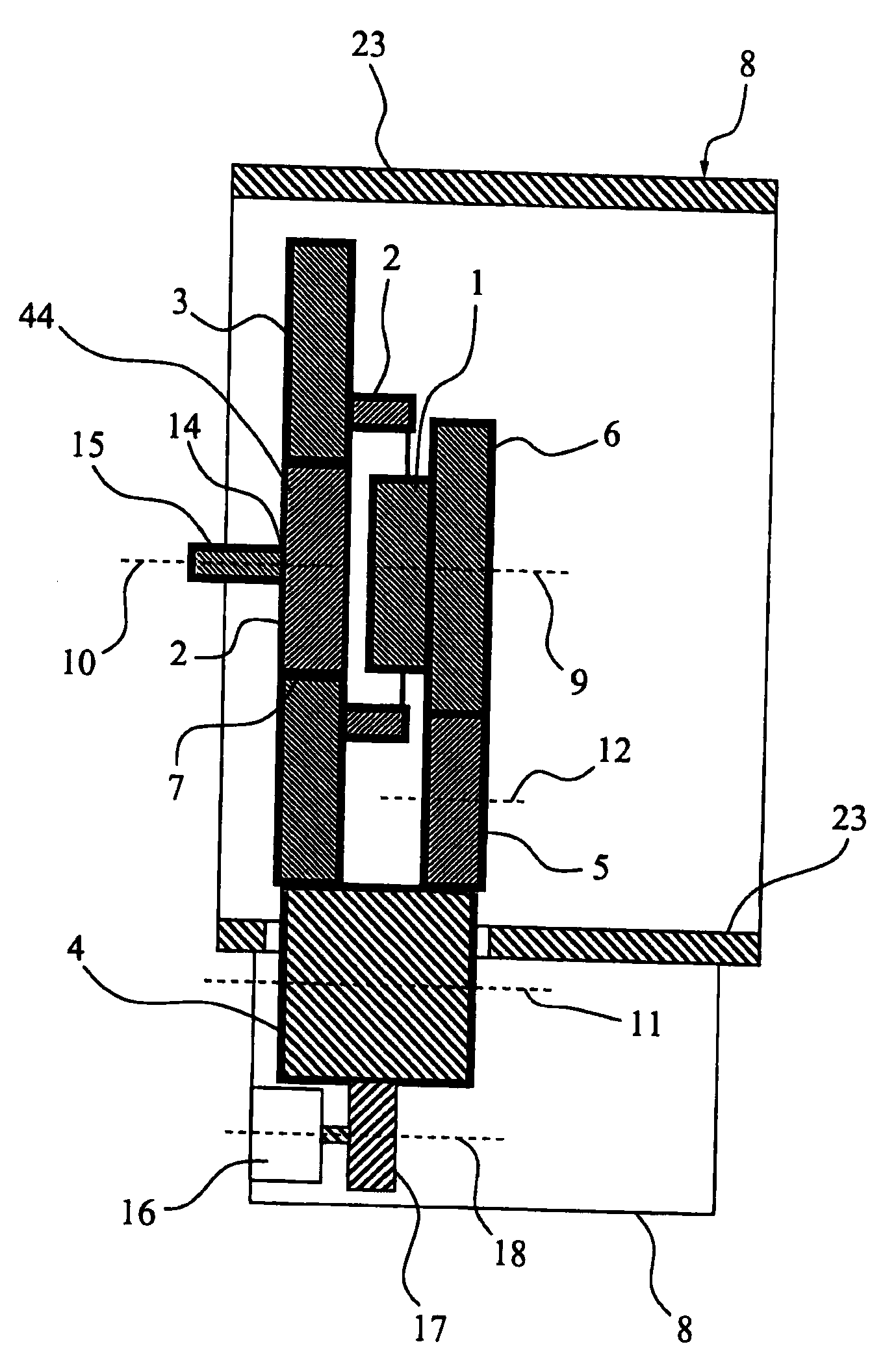
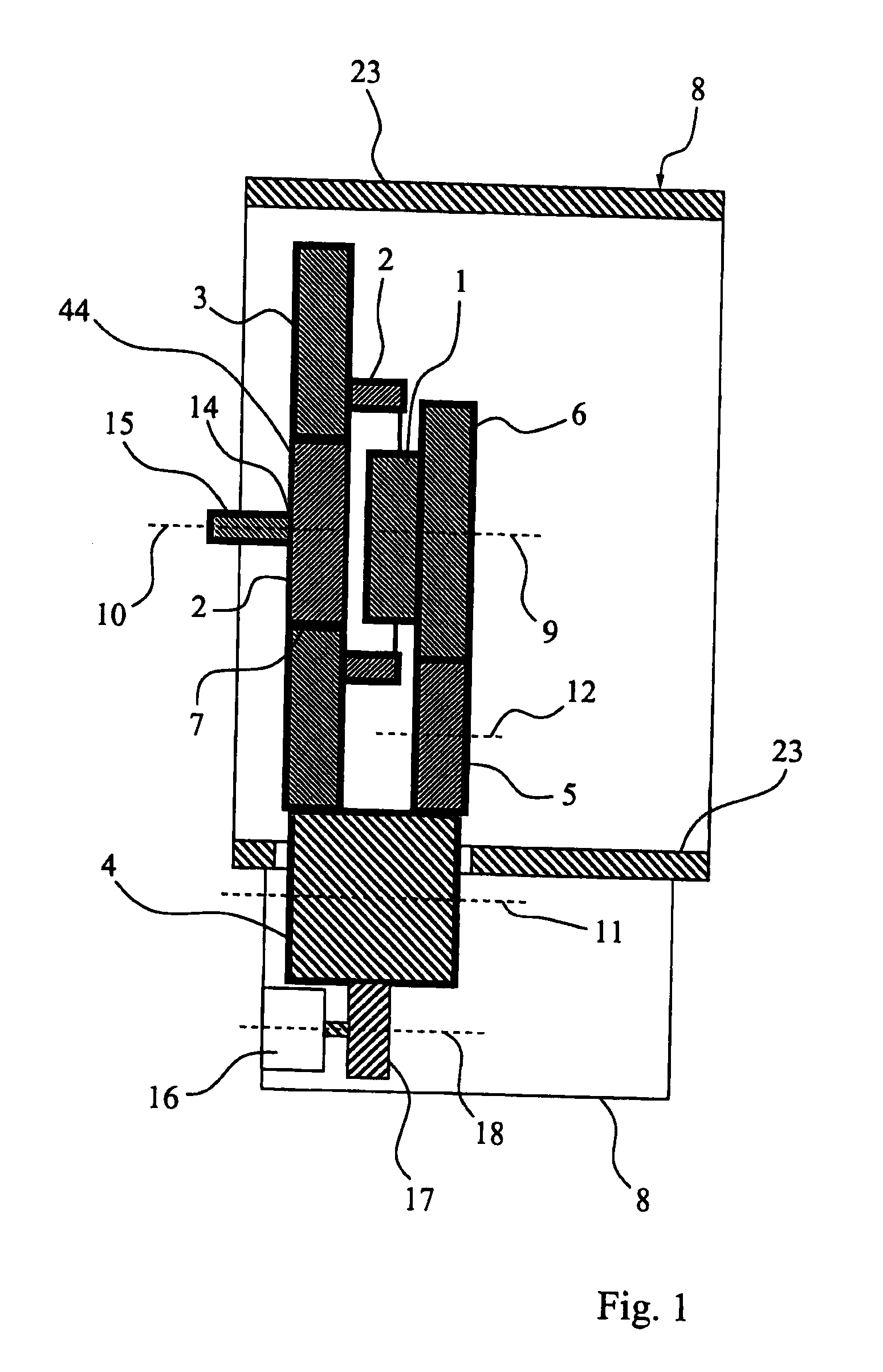
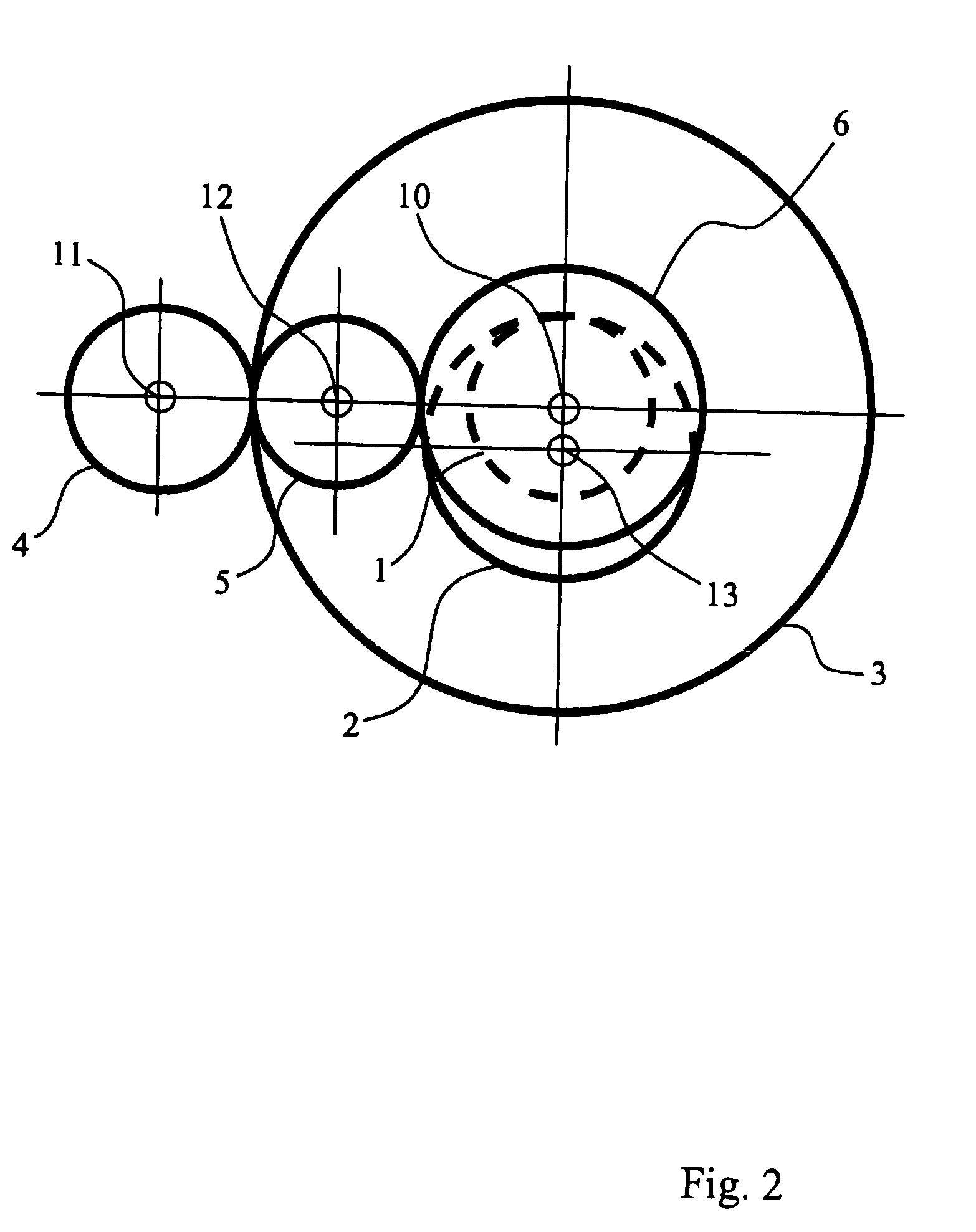
[0039]Schematic views of an adjustment drive according to the invention are seen in FIG. 1 and FIG. 2, wherein a first gear wheel 1 with outer gearing engages in inner gearing of a second gear wheel 2, which is disposed eccentrically to the first gear wheel 1. The second gear wheel 2 is furthermore disposed eccentrically to a third gear wheel 3 and supported so as to rotate therein by means of an extension 44. Outer gearing of the third gear wheel 3 engages with outer gearing of a fourth gear wheel 4, which also engage the outer teeth of a fifth gear wheel 5. A sixth gear wheel 6 is disposed concentrically to the first gear wheel 1 and connected thereto so as not to rotate, or it is configured as one piece therewith, wherein the outer teeth of the sixth gear wheel 6 engage in the outer teeth of the fifth gear wheel 5.

[0040]To this end, the rotational axis 9 of the first gear wheel 1 coincides with its center line, the rotational axis 10 of the third gear wheel 3 coincides with its c...

second embodiment

[0054]Alternatively, it is possible to also use the second embodiment, or modifications of the two embodiments, for the adjustment drive 25. In particular, two identical adjustment drives may be provided, which preferably have a common mounting 8, a common hollow-cylindrical rim 23, and / or a common drive system 16, wherein the pick-up locations 14 of both adjustment drives are located on the opposing ends of the hollow-cylindrical rim 23. In particular, the extensions 15 of the two adjustment drives extend out of the mutually opposing ends of the hollow-cylindrical rim 23.

[0055]Seen in FIG. 6 is a perspective view of an adjustment drive 25 according to the invention having a control arm 27 for connecting a vehicle wheel to an automotive body, wherein the oblong base body 28 of the steering rod 27, following the hollow-cylindrical rim 23, is formed by the mounting 8 or is fixed thereto. Furthermore, a ball joint may be fastened or disposed on the end of the control arm 27 facing away...


PUM


Abstract

An adjustment drive for local adjustment of a chassis component. The drive including a mounting (8), a first wheel (1) having a common first center line (9) and rotational axis, a second wheel (2), which is eccentric to the first wheel (1), has a second center line (13) that is parallel to the first center line (9), a third wheel (3) having a common third center line (10) and rotational axis. The third center line is either parallel to or coincident with the first center line (9). A drive system (16) is coupled to the mounting (8) and rotates at least the first and third wheels (1, 3). The second wheel (2) is eccentric to the third wheel (3) and is supported thereon so as to rotate about the second center line (13), and the first wheel (1) is coupled to the second wheel (2) for transmitting rotational motion.

Description

[0001]This application is a National Stage completion of PCT / DE2007 / 001960 filed Oct. 31, 2007, which claims priority from German patent application serial no. 10 2006 052 253.2 filed Nov. 3, 2006.FIELD OF THE INVENTION[0002]The invention relates to an adjustment drive for the local adjustment of a chassis component with a mounting, a first wheel having a first center line and rotatable around it, a second wheel that is disposed eccentrically to the first wheel and has a second center line which is oriented parallel to the first center line, a third wheel having a third center line and rotatable around it which is aligned parallel to the first center line or coincides with it, and a drive system that is coupled to the mounting from which at least the first and third wheels and can rotate. The invention further relates to the use of such an adjustment drive and to a vehicle with such an adjustment drive.BACKGROUND OF THE INVENTION[0003]Such adjustment drives are known from the state ...

Claims


Application Information

Patent Timeline
Patent Type & Authority Applications(United States)
IPC IPC(8): F16H19/02B60G7/00B62D17/00
CPCB60G7/006B60G2200/46B60G2200/462Y10T74/188B60G2204/4191B62D17/00F16H19/02B60G2204/143B60G7/00
Inventor KOCH, CHRISTOPHGARTNER, ANDREASWIESENTHAL, MARCROBINSON, DYLAN
Owner ZF FRIEDRICHSHAFEN AG
Learn More