Method and module for controlling rotation of a motorized spindle

Inactive Publication Date: 2010-03-18
BUFFALO MACHINERY +1
View PDF3 Cites 8 Cited by
  • Summary
  • Abstract
  • Description
  • Claims
  • Application Information

AI Technical Summary

Benefits of technology

[0015]a processing unit coupled to the sensing unit for receiving the voltage signal generated thereby, and outputting a control signal corresponding to the voltage signal generated by the sensing unit upon detecting that the voltage signal generated

Problems solved by technology

Vibration of high-speed spindles is considered a main cause of damage to such spindles.
On the other hand, if the predetermined vibration level of the spindle 2 is relatively low,

Method used


Image

  • Method and module for controlling rotation of a motorized spindle
  • Method and module for controlling rotation of a motorized spindle
  • Method and module for controlling rotation of a motorized spindle

Examples


Embodiment Construction

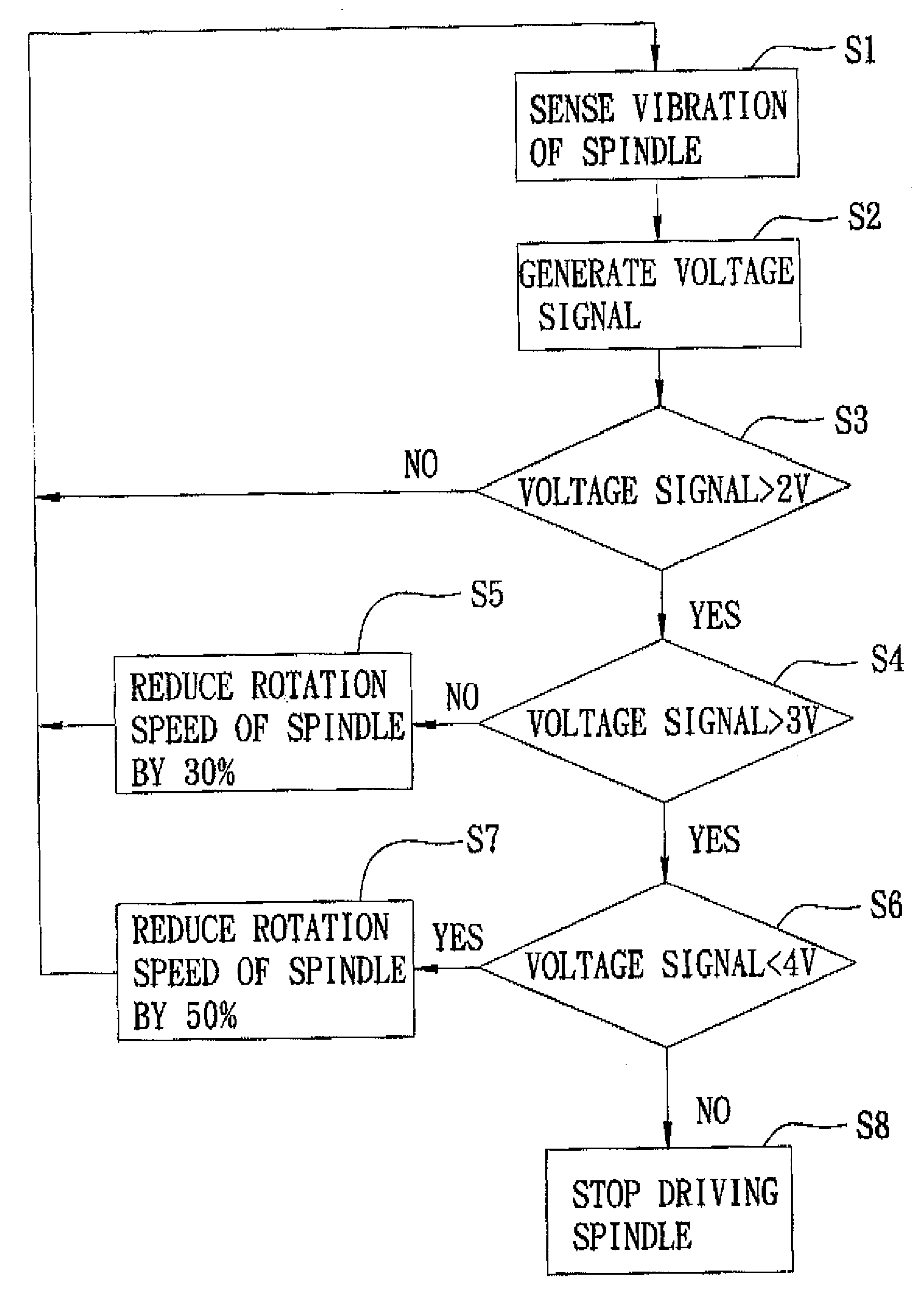
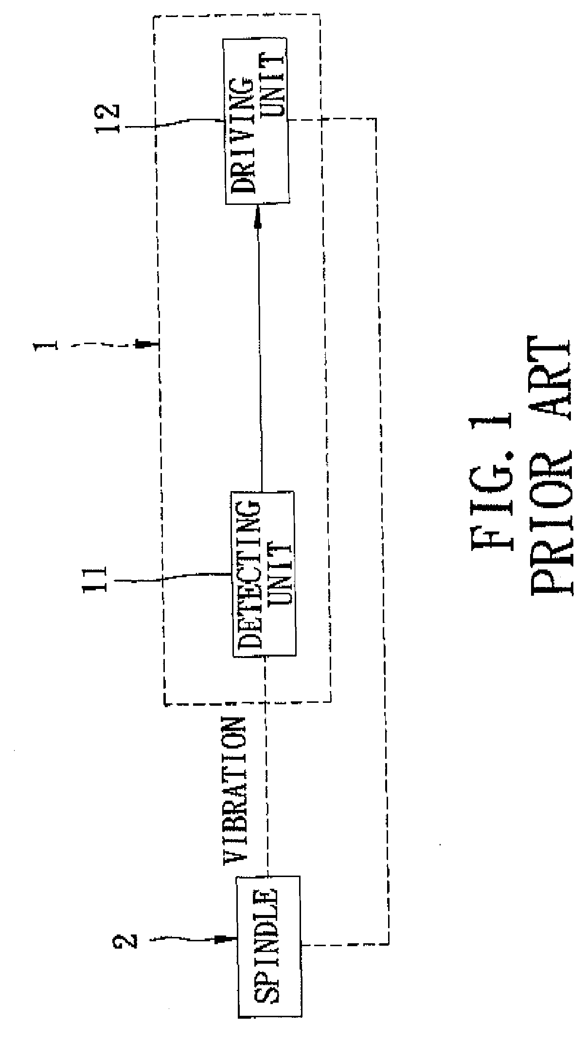
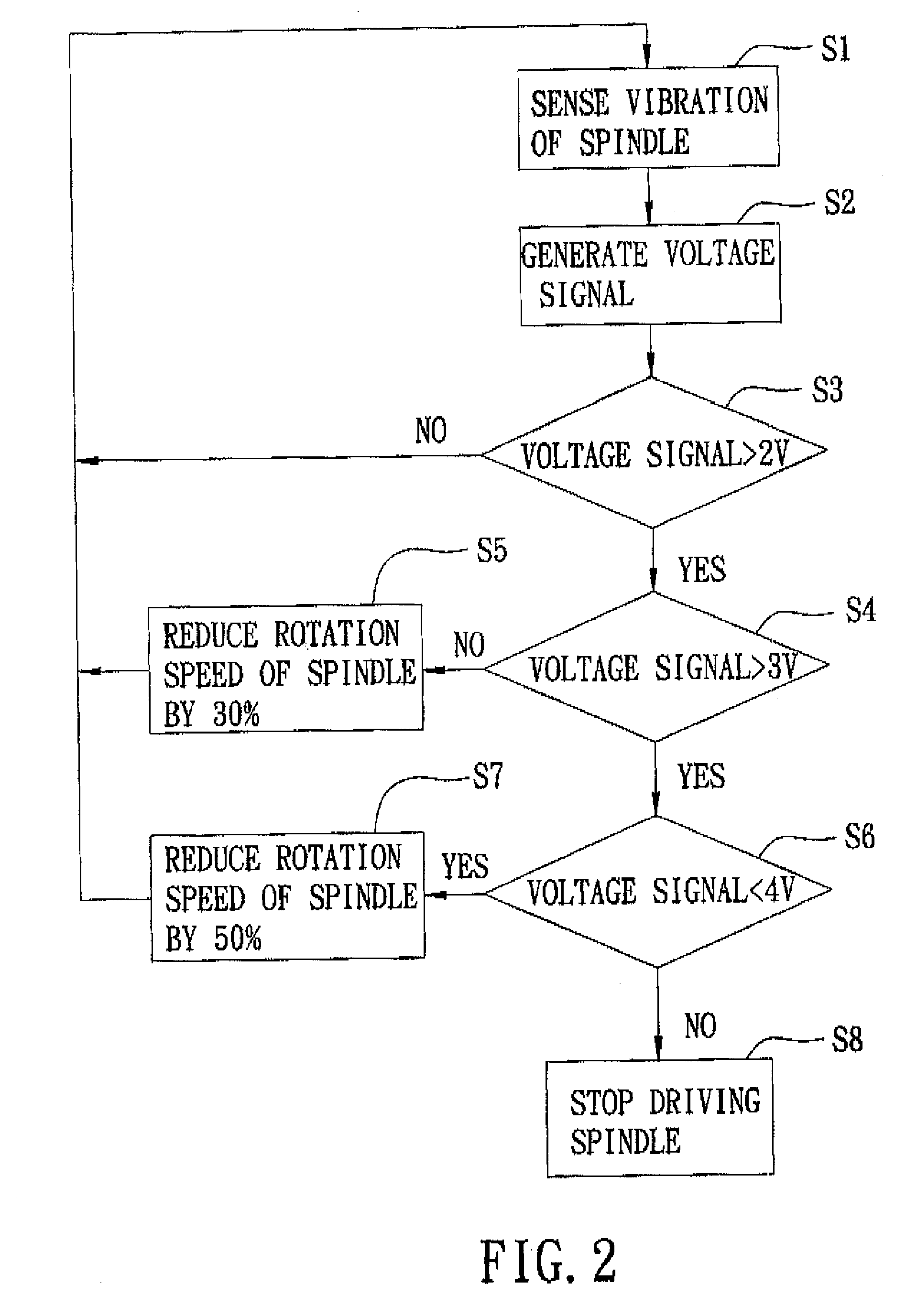
[0020]Referring to FIG. 3, a module 5 for performing the preferred embodiment of a method of controlling rotation of a motorized spindle 3 according to the present invention is shown to include a sensing unit 51 and a processing unit 52. The spindle 3 is driven by a driving unit 4 to rotate at a rotation speed.

[0021]The sensing unit 51 is adapted for sensing vibration of the spindle 3, and generates a voltage signal corresponding to the vibration of the spindle 3. In this embodiment, the sensing unit 51 includes a piezo transducer 511 for sensing the vibration of the spindle 3 and for generating a voltage output in response to the vibration of the spindle 3, and an amplifier 512 (e.g., an operational amplifier) coupled to the piezo transducer 511 for amplifying the voltage output to result in the voltage signal.

[0022]The processing unit 52 is coupled to the amplifier 512 of the sensing unit 51 for receiving the voltage signal generated by the sensing unit 51, and is adapted to outpu...


PUM


Abstract

In a method and module for controlling rotation of a motorized spindle driven by a driving unit, a sensing unit is adapted for sensing vibration of the spindle and generates a voltage signal corresponding to the vibration of the spindle. A processing unit is coupled to the sensing unit for receiving the voltage signal therefrom, and outputs a control signal corresponding to the voltage signal upon detecting that the voltage signal is greater than a reference voltage corresponding to a predetermined vibration level of the spindle, such that the driving unit adjusts a rotation speed of the spindle in response to the control signal from the processing unit.

Description

BACKGROUND OF THE INVENTION[0001]1. Field of the Invention[0002]The invention relates to a method and module for controlling rotation of a motorized spindle.[0003]2. Description of the Related Art[0004]Vibration of high-speed spindles is considered a main cause of damage to such spindles.[0005]Referring to FIG. 1, a conventional driving device 1 for a motorized spindle 2 is shown to include a detecting unit 11, and a driving unit 12 for driving the spindle 2. The detecting unit 11 generates a detecting signal upon detecting that vibration of the spindle 2 is greater than a predetermined vibration level, and outputs the detecting signal to the driving unit 12. The driving unit 12 stops driving the spindle 2 or reduces a rotation speed of the spindle 2 in accordance with the detecting signal from the detecting unit 11.[0006]In such a driving device 1, it is important to appropriately decide the predetermined vibration level of the spindle 2. For example, if the predetermined vibration...

Claims


Application Information

Patent Timeline
IPC IPC(8): H02P23/04
CPCH02P23/04
Inventor CHANG, PAULCHEN, TSAIR-RONGROW, JEEN-SHEENLU, CHIN-SHENG
Owner BUFFALO MACHINERY
Why Eureka
Try Eureka