X-ray CT imaging apparatus and imaging control method therefor

a technology of ct imaging and control method, which is applied in the field of x-ray ct imaging apparatus and imaging control method therefor, can solve the problems of complex apparatus, high cost, and constant supply of excess x-rays, and achieves simple configuration, low cost, and the effect of reducing the influence of the high x-ray absorption region

Active Publication Date: 2010-03-18
MORITA MFG CO LTD +1
View PDF4 Cites 35 Cited by
  • Summary
  • Abstract
  • Description
  • Claims
  • Application Information

AI Technical Summary

Benefits of technology

[0015]It is thereby possible alleviate the influence of the high X-ray absorption region, present inside the object, with a simple configuration at low cost, to perform CT imaging.
[0016]Further, an X-ray CT imaging apparatus according to a third aspect further includes: a central axis setting section for setting a position of a rotation central axis of the X-ray generating section and the X-ray image capturing section; and a rotation central axis shifting section for shifting the position of the rotation...

Problems solved by technology

In the X-ray CT imaging apparatus, when a large bone structure or the like is reflected in a plurality of pieces of X-ray imaged image information at the time of CT image processing, a large amount of X-rays is absorbed in that portion, thereby making it difficult to obtain a clear CT image.
H10-225454, the need for providing the gain adjustment circuit in the X-ray imaging means causes problems of making the apparatus itself complex and cost high.
H10-225454 is control in accordance...

Method used


Image

  • X-ray CT imaging apparatus and imaging control method therefor
  • X-ray CT imaging apparatus and imaging control method therefor
  • X-ray CT imaging apparatus and imaging control method therefor

Examples


embodiment 1

[0072]In the following described is an example of an X-ray imaging apparatus (X-ray CT imaging apparatus) that is used in the dental field and performs CT imaging of a maxillofacial area of an object.

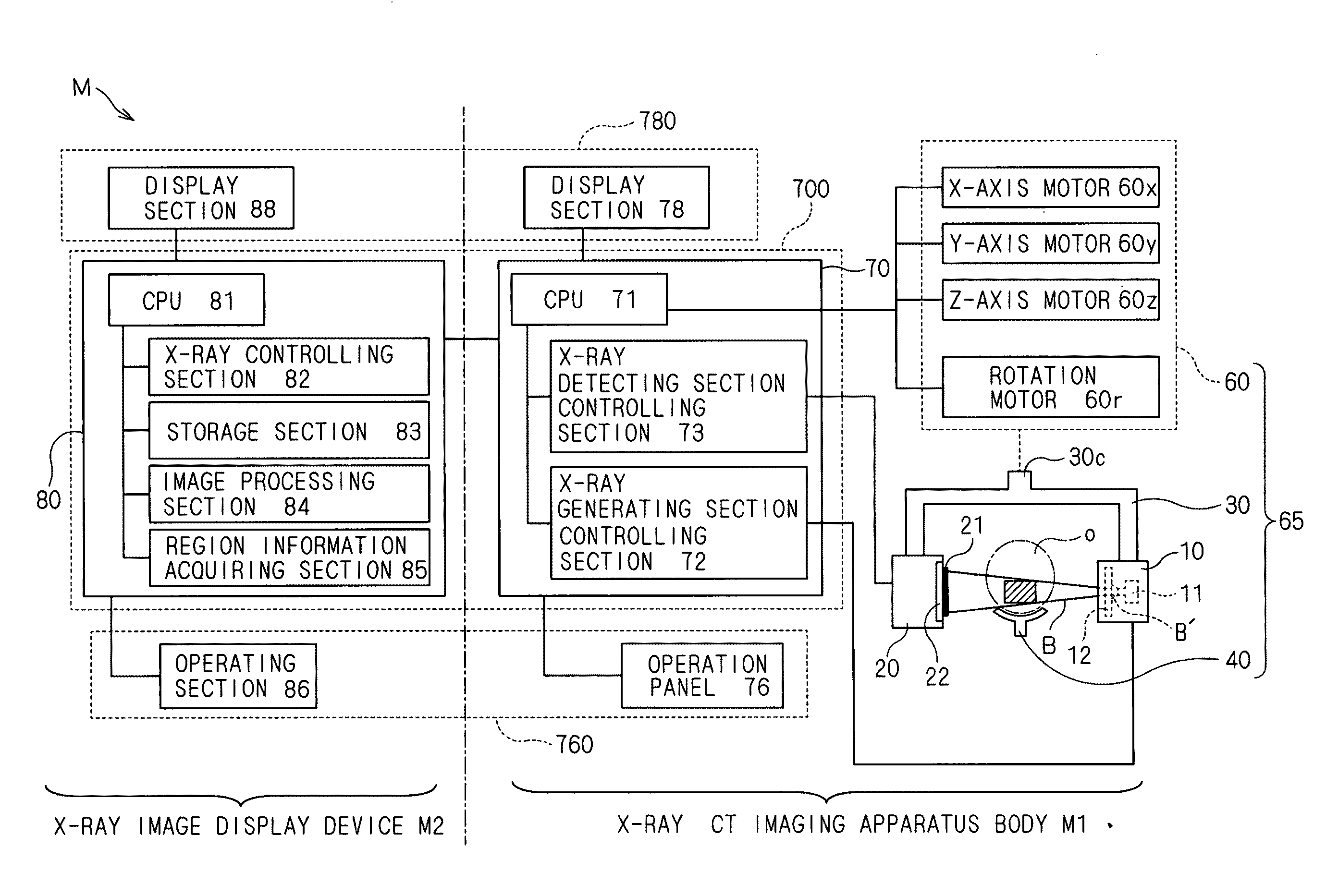
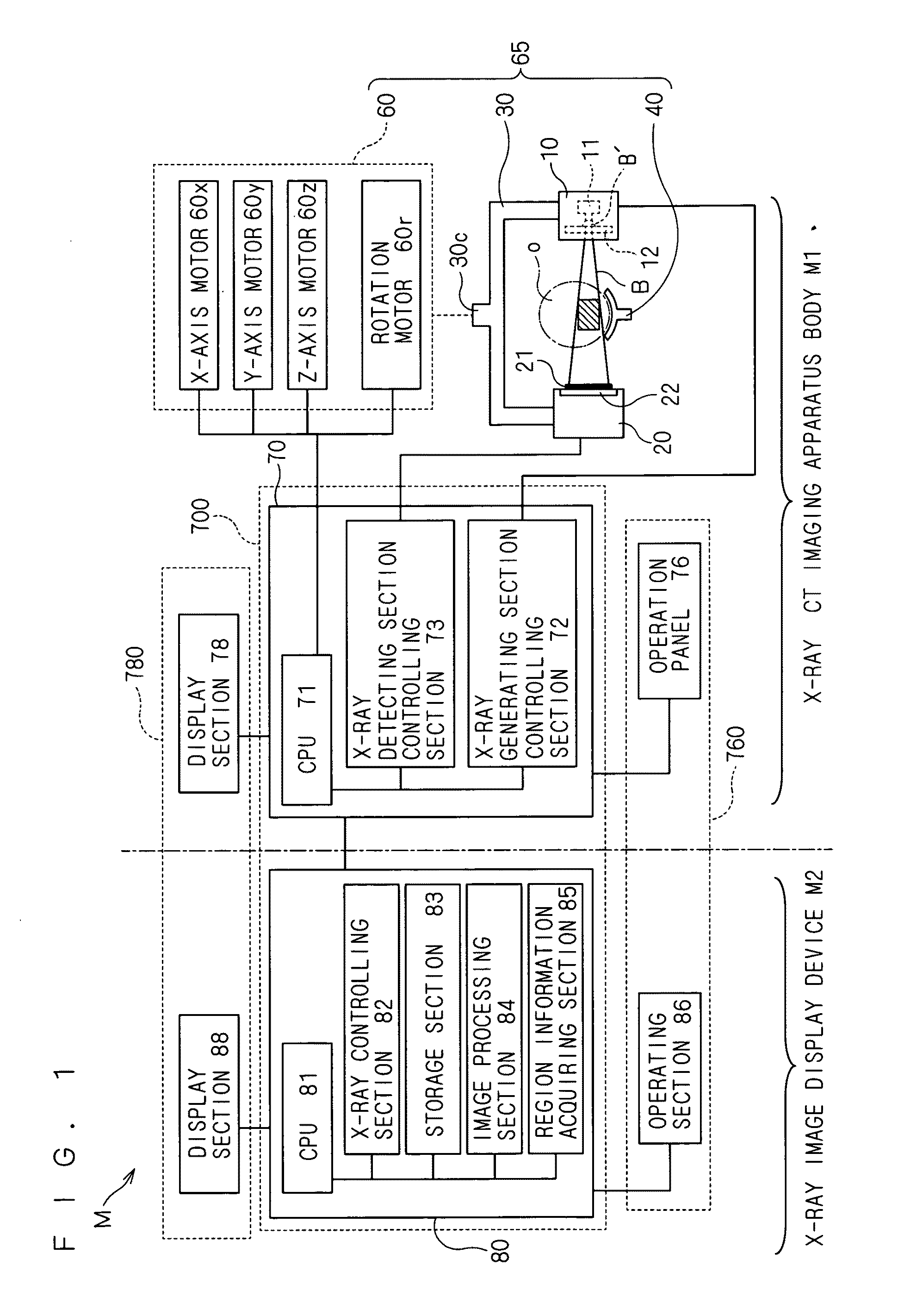
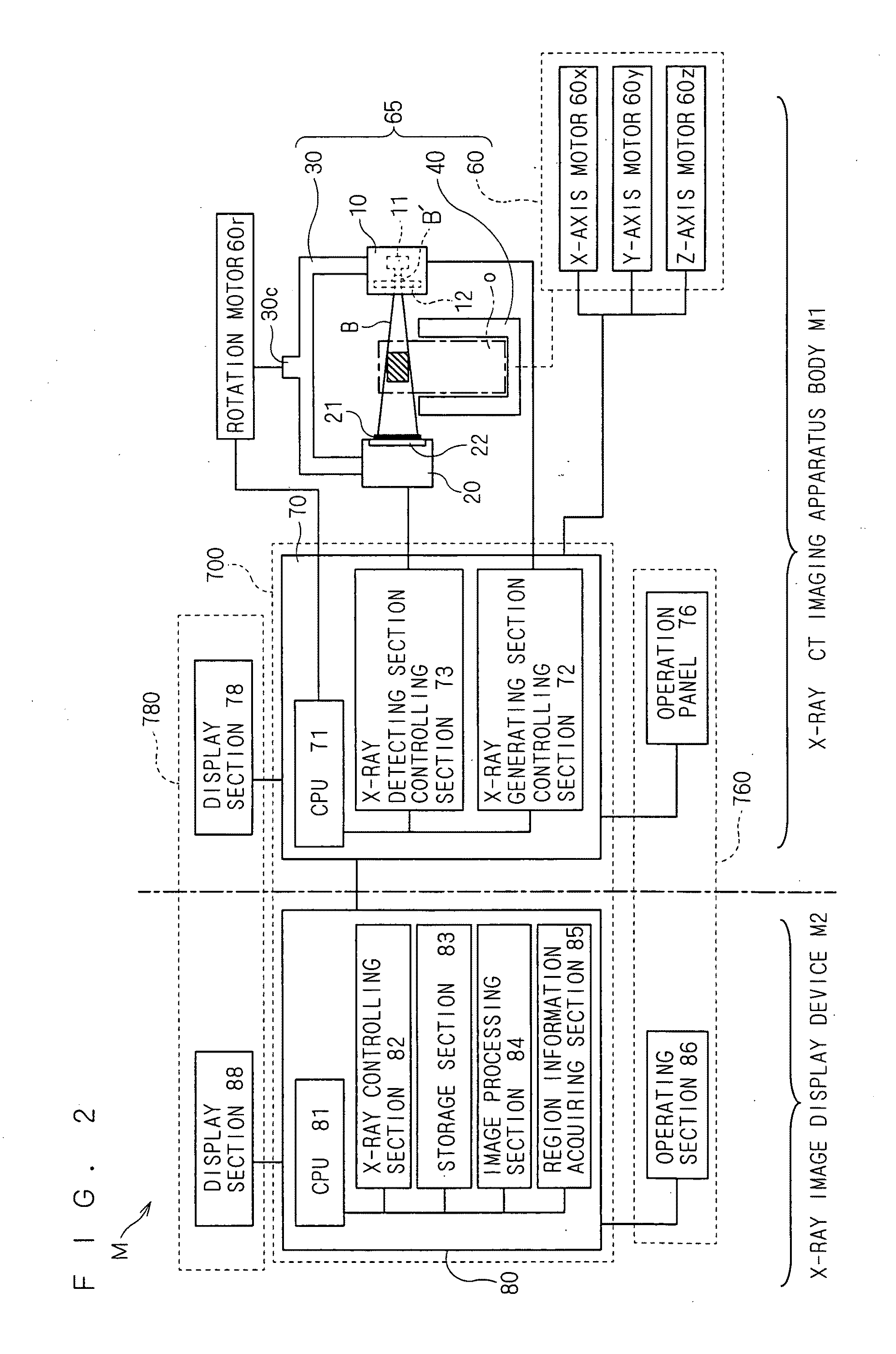
[0073]FIG. 1 is a block diagram explaining a basic configuration of an X-ray CT imaging apparatus M. The X-ray CT imaging apparatus M includes an X-ray CT imaging apparatus body M1 and an X-ray image display device M2, and has a configuration of these transmitting and receiving data through a communication cable or the like.

[0074]The X-ray CT imaging apparatus body M1 includes: a supporting section 30 that supports an X-ray generating section 10 and an X-ray image capturing section 20 in a mutually opposed manner; a driving section 60 that drives the supporting section 30; and an imaging apparatus controlling section 70, and the imaging apparatus controlling section 70 is added with an operation panel 76. This operation panel 76 is used for the purpose of setting the X-ray generating se...

embodiment 2

[0110]In the X-ray CT imaging apparatus M according to Embodiment 1, it was necessary for obtaining high X-ray absorption region information to designate the region displayed on the scout image or the like by the operation section 86. On the other hand, in an X-ray CT imaging apparatus M according to the present embodiment, information on the region which is displayed on a scout image or the like is acquired through use of image pattern recognition.

[0111]Specifically, an operation of the X-ray CT imaging apparatus M according to the present embodiment is described by use of a flowchart shown in FIG. 10. First, in Step S21 shown in FIG. 10, auxiliary X-ray imaging is executed for obtaining a scout image or the like. It is to be noted that an image taken in the auxiliary X-ray imaging may be a single-shot fluoroscopic image, a bidirectional scout image, or a panorama scout image. Further, in Step S22, an X-ray image obtained in the auxiliary X-ray imaging is generated as in FIG. 11A.

[...

embodiment 3

[0115]In an X-ray CT imaging apparatus M according to the present embodiment, a control model previously set based upon a size of the object o (patient) is selected to alleviate an influence of a high X-ray absorption region, to perform CT imaging.

[0116]Specifically, an operation of the X-ray CT imaging apparatus M according to the present embodiment is described by use of a flowchart shown in FIG. 13. First, in Step S31, an image shown in FIG. 14 is displayed on the operation panel 76 in FIG. 1 and the like. FIG. 14(a) is a screen with the CT imaging area R set to a diameter of 40 mm and a height of 40 mm, and “40×40” has been selected in a CT imaging area size selection button 741. Meanwhile, FIG. 14(b) is a screen with the CT imaging area R set to a diameter of 140 mm and a height of 100 mm, and “140×100” has been selected in the CT imaging area size selection button 741. Further, in FIGS. 14(a) and 14(b), a patient size (head size) has been set to “M” by means of a patient size ...


PUM


Abstract

An X-ray CT imaging apparatus includes an X-ray generating section, an X-ray image capturing section, a supporting section, a holding section, a rotation driving section, and an X-ray controlling section, wherein the X-ray generating section generates an X-ray cone beam, the X-ray image capturing section detects the X-ray cone beam having passed through an object, the supporting section supports the X-ray generating section and the X-ray image capturing section with the object positioned therebetween, the holding section holds the object, the rotation driving section rotates the supporting section relatively to the object, and the X-ray controlling section alleviates an influence of a high X-ray absorption region, present inside the object, in the X-ray image capturing section by means of a control model formed based upon information on the high X-ray absorption region.

Description

BACKGROUND OF THE INVENTION[0001]1. Field of the Invention[0002]The present invention relates to an X-ray CT imaging apparatus and an imaging control method therefor, and particularly relates to an X-ray CT imaging apparatus and an imaging control method therefor, which are capable of alleviating an influence of a high X-ray absorption region that is present inside an object and has an influence on an imaging result.[0003]2. Description of the Background Art[0004]In the field of X-ray diagnosis for medical use, an X-ray CT (computerized tomography) imaging apparatus for tomographically imaging an arbitrary region of a human body is widely known. In this X-ray CT imaging apparatus, an X-ray generating section and an X-ray imaging means being opposed thereto are rotated 360 degrees around an object, and obtained image information is subjected to computer processing, to obtain an CT image of an arbitrary region of a head, a body or the like having been cut off.[0005]Especially in the f...

Claims


Application Information

Patent Timeline
IPC IPC(8): H05G1/46H05G1/32H05G1/60
CPCA61B6/032A61B6/544A61B6/542A61B6/14
Inventor ARAI, YOSHINORIYOSHIMURA, TAKAHIROYOSHIKAWA, HIDEKI
Owner MORITA MFG CO LTD
Why Eureka
Try Eureka