Clogging determining device for reducing agent passage and clogging determining method for reducing agent passage

Active Publication Date: 2010-03-25
BOSCH CORP
View PDF1 Cites 68 Cited by
  • Summary
  • Abstract
  • Description
  • Claims
  • Application Information

AI Technical Summary

Benefits of technology

[0019]According to the clogging determining device for the reducing agent passage of the present invention, the device is shifted to a test mode to stop the pump when the pump is not indicative of predetermined driving DUTY, and the pressure variation in the first reducing agent passage extending from the pump when the reducing agent injection valve is fully opened and intercommunicating with the reducing agent injection valve is detected, whereby it can be estimated whether clogging occurs at any place in the first reducing agent passage or the second reducing agent passage. Accordingly, a work of specifying the clogged place can be omitted and the number of parts to be repaired/exchanged can be reduced, whereby the maintenance work can be efficiently performed.
[0020]Still furthermore, in the clogging determining device for the reducing agent passage according to this invention, the possibility of occurrence of clogging in the first reducing agent passage can be determined by detecting abnormality of the driving DUTY of the pump when the reducing agent injection valve is opened at a predetermined opening degree or more.
[0021]Still furthermore, in the clogging determining device for the reducing agent passage according to this invention, the clogging in the first reducing agent passage can be more accurately estimated by determining whether the pressure reduction amount in the first reducing agent passage is not less than a predetermined reference value under a predetermined state. Accordingly, the clogging-suspected first reducing agent passage can be selected and accurately repaired/exchanged.
[0022]Still furthermore, in the clogging

Problems solved by technology

Here, in the case where urea solution is used as reducing agent, hydrolysis occurs in the urea solution and thus it is crystallized when the ure

Method used


Image

  • Clogging determining device for reducing agent passage and clogging determining method for reducing agent passage
  • Clogging determining device for reducing agent passage and clogging determining method for reducing agent passage
  • Clogging determining device for reducing agent passage and clogging determining method for reducing agent passage

Examples


Example

First Embodiment

[0037]1. Clogging Determining Device for Reducing Agent Passage

[0038](1) Whole Construction of Exhaust Gas Purification System

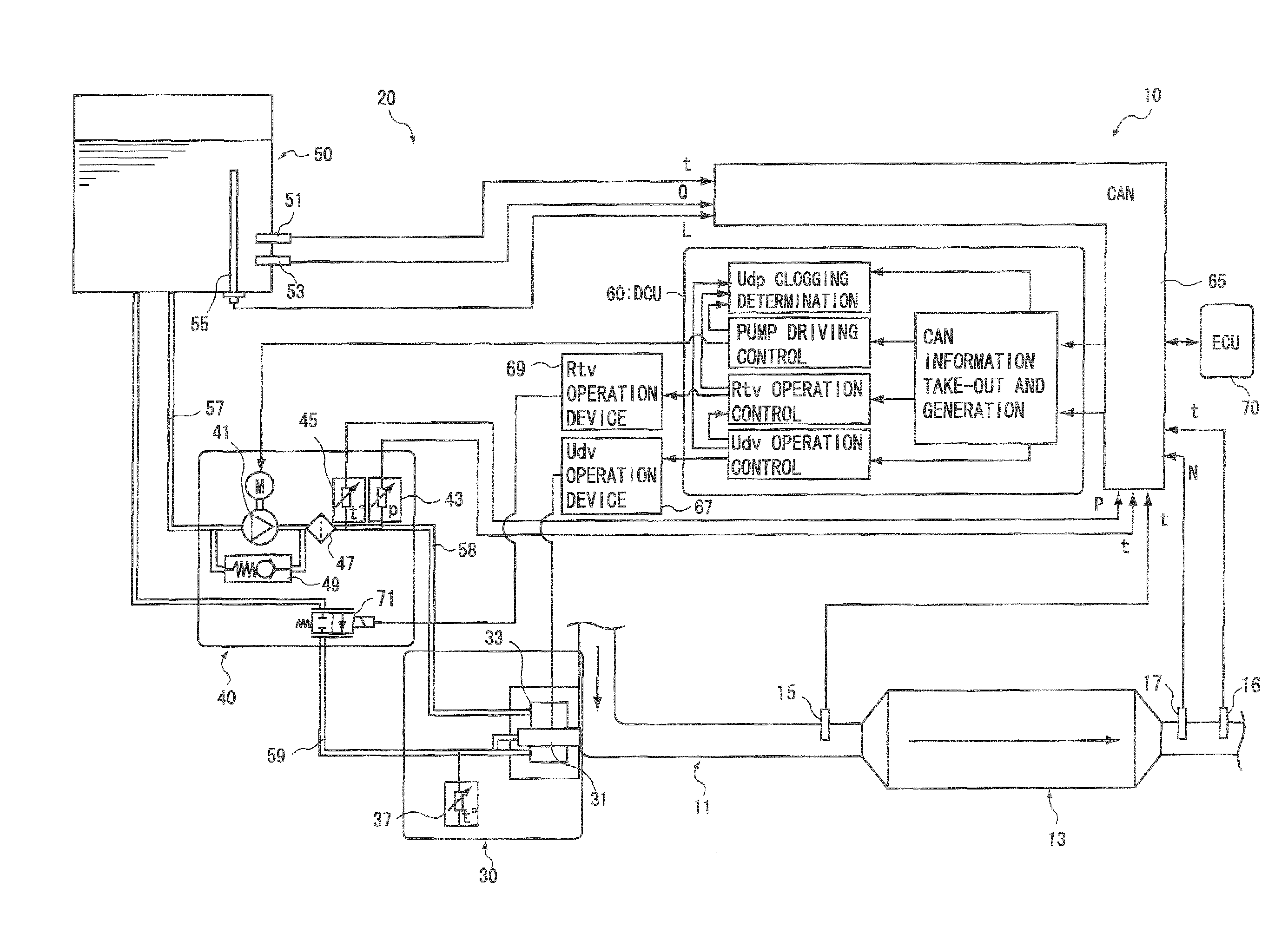
[0039]First, an example of the construction of an exhaust gas purification system having a clogging determining device for a reducing agent passage according to an embodiment (hereinafter referred to as “system” in some cases) will be described with reference to FIG. 1.

[0040]The exhaust gas purification system 10 shown in FIG. 1 is an exhaust gas purification system 10 in which urea water solution is used as reducing agent and exhaust gas is passed through NOx catalyst 13 together with the reducing agent to thereby selectively reduce NOR. This exhaust gas purification system 10 is provided with an NOx catalyst 13 for selectively reducing NOx contained in exhaust gas which is disposed at some midpoint of an exhaust gas passage 11 connected to an internal combustion engine and a reducing agent supply device 20 containing a reducing agent injecti...

Example

Second Embodiment

[0085]1. Clogging Determining Device for Reducing Agent Passage

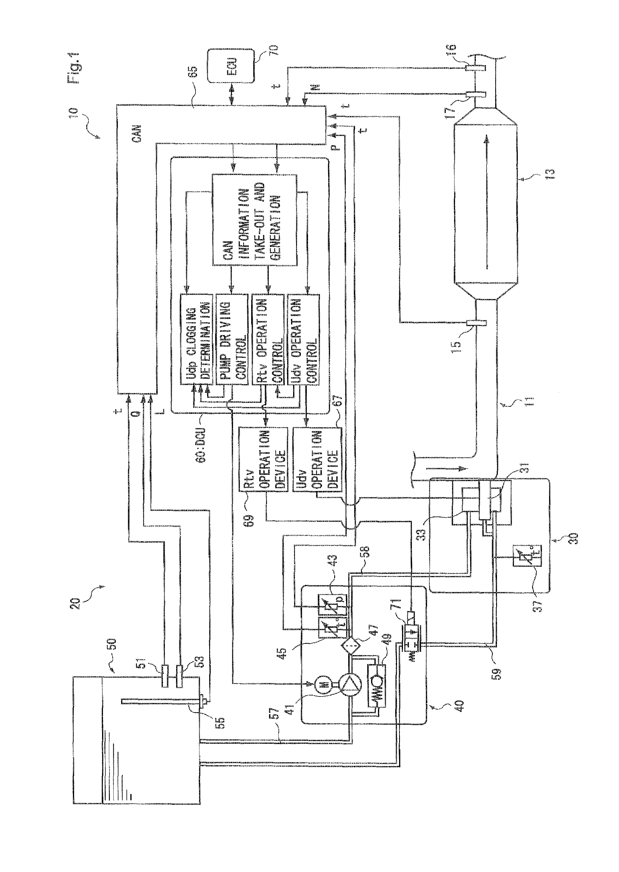
[0086]An example of the construction of an exhaust gas purification system having a clogging determining device for a reducing agent passage according to this embodiment (hereinafter referred to as “system” in some cases) is shown in FIG. 4.

[0087]The exhaust gas purification system 100 shown in FIG. 4 is constructed so that an orifice 35 is provided in place of the return valve 71 provided to the circulating passage 59 in the exhaust gas purification system 10 of the first embodiment shown in FIG. 1.

[0088]That is, the injection module 30 in the exhaust gas purification system 100 of this embodiment has a pressure chamber 33 in which reducing agent pressure-fed from the pump module 40 side is stocked, a reducing agent injection valve 31 connected to the pressure chamber 33, an orifice 35 disposed at some midpoint of a passage extending from the pressure chamber 33 and intercommunicating with a circulating...

Example

Third Embodiment

[0100]1. Whole Construction of Exhaust Gas Purification System

[0101]An exhaust gas purification system having a clogging determining device for a reducing agent passage according to this embodiment is different from the exhaust gas purification system of the first embodiment in the construction of the reducing agent passage of the reducing agent supply device.

[0102]FIG. 6 shows an example of the construction of the exhaust gas purification system 110 according to this embodiment, and the same constituent elements of the exhaust gas purification system of the first embodiment are used as the constituent elements other than the reducing agent supply device 120.

[0103]The reducing agent supply device 120 provided to the exhaust gas purification system 110 of this embodiment has a reducing agent injection valve 131, a storage tank 150 in which reducing agent is stocked, a pump module 140 containing a pump 141 for pressure-feeding reducing agent in the storage tank 150 to ...


PUM

PropertyMeasurementUnit
Temperatureaaaaaaaaaa
Pressureaaaaaaaaaa

Abstract

There are provided a clogging determining device for a reducing agent passage and a clogging determining method for a reducing agent passage, which can accurately detect clogging and estimate a clogged place when clogging occurs in any place of a supply line or a return line.
The device includes pump driving control means for subjecting the pump to DUTY control so that a pressure value is kept to a predetermined value, driving DUTY determining means for determining whether the driving DUTY of the pump is less than a predetermined threshold value corresponding to the opening degree of the reducing agent injection valve, or not; pressure reduction amount calculating means for calculating a pressure reduction amount by which the pressure value detected by the pressure sensor is reduced within a predetermined time after the pump is stopped and the reducing agent injection valve is fully opened when it is determined that the driving DUTY of the pump is less than the threshold value, and clogging determining means for determining on the basis of the pressure reduction amount calculated by the pressure reduction amount: calculating means whether clogging occurs in the first reducing agent passage or the second reducing agent passage.

Description

TECHNICAL FIELD[0001]The present invention relates to a clogging determining device for a reducing agent passage and a clogging determining method for a reducing agent passage in an exhaust gas purification system. Particularly, the present invention relates to a clogging determining device for a passage and a clogging determining method for a reducing agent passage in an exhaust gas purification system having a return passage for keeping reducing agent under low temperature.BACKGROUND ART[0002]Oxides of nitrogen (hereinafter referred to as NON) which may risk the environment are contained in exhaust gas discharged from an internal combustion engine such as a diesel engine or the like. As an exhaust gas purification system used for purifying NOx there has been known an exhaust gas purification system (SCR system) for injecting and mixing urea solution as reducing agent into exhaust gas and selectively reducing and purifying NOx with catalyst.[0003]Here, in the case where urea soluti...

Claims


Application Information

Patent Timeline
IPC IPC(8): F01N11/00F01N3/18F01N3/28
CPCB01D2251/2067B01D2257/404F01N3/2066F01N11/00Y02T10/24F01N2610/02F01N2610/14Y02T10/47F01N2550/05Y02T10/12Y02T10/40B01D53/86B01D53/94F01N3/04F01N3/08
Inventor KITAZAWA, EIICHI
Owner BOSCH CORP
Why Eureka
Try Eureka