Gas Turbine Transition Duct

Active Publication Date: 2010-03-25
SIEMENS ENERGY INC
View PDF21 Cites 64 Cited by
  • Summary
  • Abstract
  • Description
  • Claims
  • Application Information

AI Technical Summary

Problems solved by technology

The expansion of the combustion gas through the rows of rotating blades and stationary vanes in the turbine assembly results in a transfer of energy from the combustion gas to the rotating assembly, causing rotation of the shaft.
Such cooling is typically required, as the materials forming the forward cone section and the intermediate exit piece, if not cooled, may become overheated, which may cause undesirable consequences, such as deterioration of the transition duct.

Method used


Image

  • Gas Turbine Transition Duct
  • Gas Turbine Transition Duct
  • Gas Turbine Transition Duct

Examples


Embodiment Construction

[0017]In the following detailed description of the preferred embodiment, reference is made to the accompanying drawings that form a part hereof, and in which is shown by way of illustration, and not by way of limitation, a specific preferred embodiment in which the invention may be practiced. It is to be understood that other embodiments may be utilized and that changes may be made without departing from the spirit and scope of the present invention.

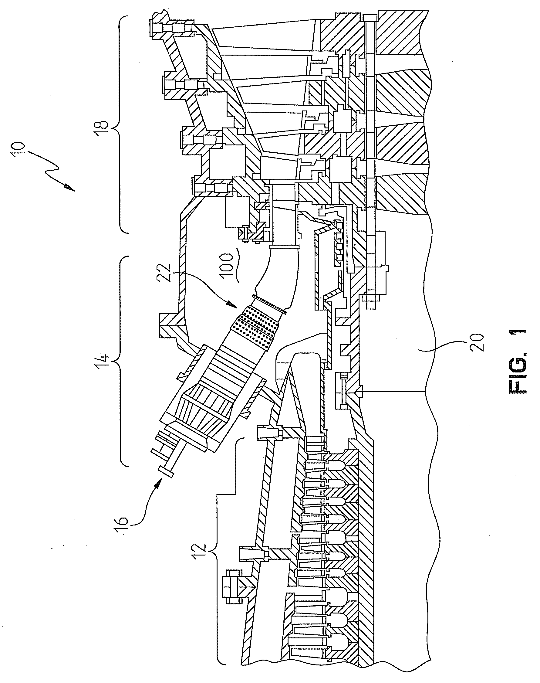
[0018]Referring to FIG. 1, a portion of a gas turbine engine 10 is shown. The engine 10 includes a compressor section 12, a combustion section 14 including a plurality of combustors 16 (only one shown), and a turbine section 18. The compressor section 12 inducts and pressurizes inlet air which is directed to the combustors 16 in the combustion section 14. Upon entering the combustors 16, the compressed air from the compressor section 12 is mixed with a fuel and ignited produce a high temperature and high velocity combustion gas flowing i...


PUM


Abstract

A transition member between a combustion section and a turbine section in a gas turbine engine. The transition member includes a casing inner wall and a plurality of spanning members. The spanning members extend radially outwardly from a radially outer surface of the casing inner wall. Each of the spanning members included a slot formed therein. Each slot is in communication with a first aperture formed in the radially inner surface of the casing inner wall and a plurality of second apertures formed in an aft side of the spanning member for effecting a passage of the cooling fluid from a first cooling fluid channel to an inner volume defined within the radially inner surface of the casing inner wall. The slots include a component in the radial direction and a component in the axial direction such that the first aperture is not radially aligned with the second apertures.

Description

CROSS-REFERENCE TO RELATED APPLICATION[0001]This application claims the benefit of U.S. Provisional Application Ser. No. 61 / 100,097 entitled COOLING SYSTEM FOR A TRANSITION DUCT AND RELATED METHOD, filed Sep. 25, 2008, the entire disclosure of which is incorporated by reference herein.FIELD OF THE INVENTION[0002]The present invention relates to gas turbine engines and, more particularly, to a transition duct and a cooling thereof, wherein the transition duct conveys hot combustion gases from a combustion section of the engine to a turbine section.BACKGROUND OF THE INVENTION[0003]Generally, gas turbine engines have three main sections or assemblies, including a compressor assembly, a combustor assembly, and a turbine assembly. In operation, the compressor assembly compresses ambient air. The compressed air is channeled into the combustor assembly where it is mixed with a fuel and ignites, creating a working combustion gas. The combustion gas is expanded through the turbine assembly. ...

Claims


Application Information

Patent Timeline
IPC IPC(8): F02C7/12F23R3/42
CPCF01D9/023F23R3/005F23R3/06F05D2260/202F23R2900/03044F23R2900/03045F05D2260/201F23R2900/03042
Inventor LIANG, GEORGE
Owner SIEMENS ENERGY INC
Why Eureka
Try Eureka