Hollow tissue inosculation apparatus

a technology of inosculation apparatus and hollow tissue, which is applied in the direction of manufacturing tools, surgical staples, paper/cardboard containers, etc., can solve the problem of dangerous mixing of these into the blood vessel

Inactive Publication Date: 2010-03-25
OLYMPUS CORP
View PDF30 Cites 8 Cited by
  • Summary
  • Abstract
  • Description
  • Claims
  • Application Information

AI Technical Summary

Benefits of technology

[0007]The present invention is directed to a hollow tissue inosculation apparatus to inosculate two hollow tissues to each other with a staple having a plurality of elastically deformable bent staple pins. The hollow tissue inosculation apparatus includes a staple holder to hold the staple, a curvature control mechanism to control curvature of the staple pins of the staple held in the staple holder, an incision mechanism to incise the hollow tissues, and a gap control mechanis

Problems solved by technology

In the above-mentioned apparatus, since a blood vessel is incised with the blade of the cutter being in contact with the ring member, undesira

Method used


Image

  • Hollow tissue inosculation apparatus
  • Hollow tissue inosculation apparatus
  • Hollow tissue inosculation apparatus

Examples


first embodiment

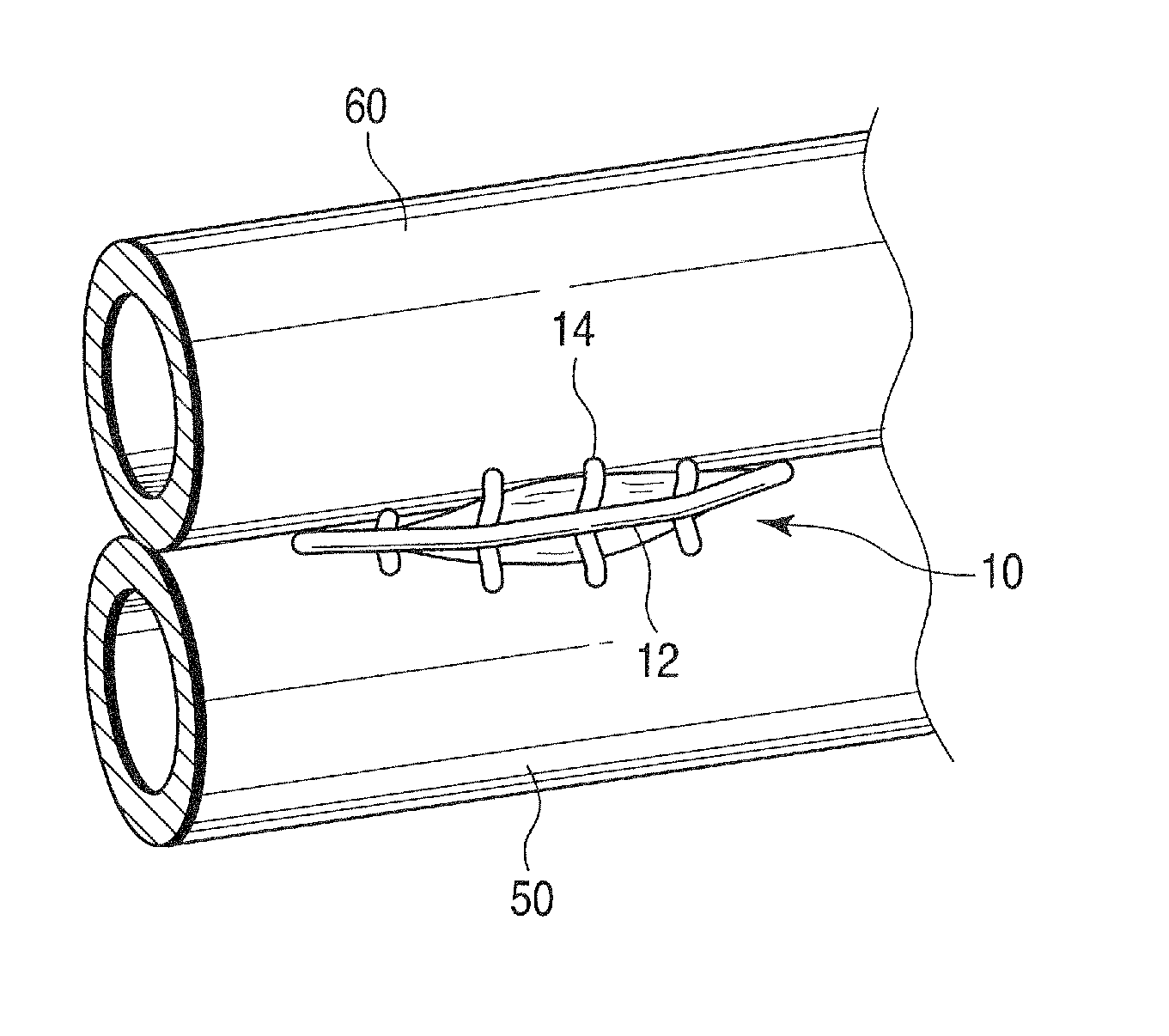
[0076]The present embodiment concerns a staple and a hollow tissue inosculation apparatus to inosculate two hollow tissues to each other. The hollow tissues are specifically blood vessels.

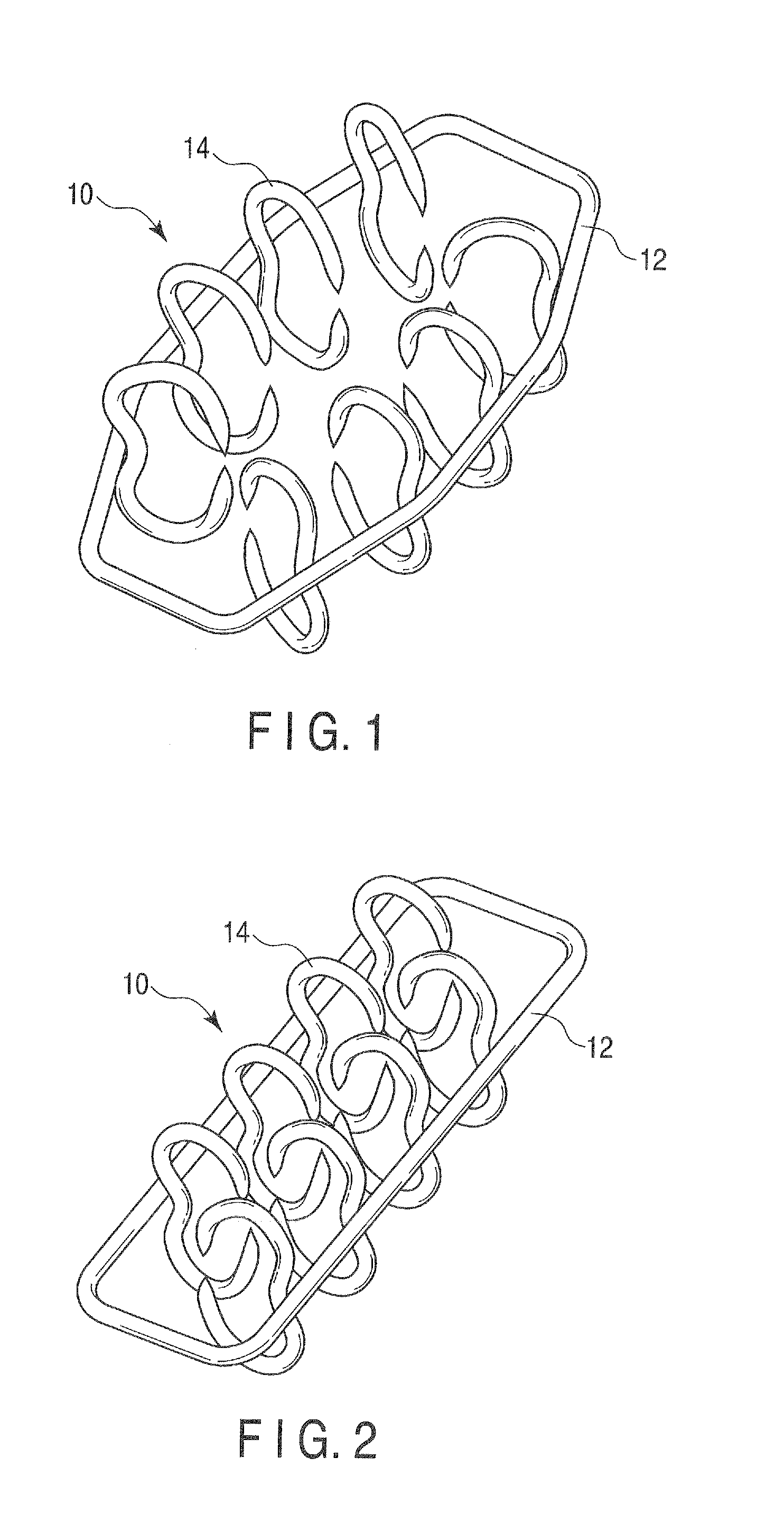
[0077]The staple as a fastening to inosculate two hollow tissues will be first described with reference to FIGS. 1 and 2. Each of FIGS. 1 and 2 is a perspective view of the staple according to the present embodiment. FIG. 1 shows the staple in a natural state, and FIG. 2 shows the staple attached to the hollow tissue inosculation apparatus.

[0078]As shown in FIGS. 1 and 2, the staple 10 has an elastically deformable generally ring-like ring member 12 and a plurality of elastically deformable bent staple pins 14. Each staple pin 14 is fixed on the inner side of the ring member 12. An axis of the ring member 12 is on a plane, an axis of each staple pin 14 is on a different plane, and these planes are generally perpendicular to each other. Here, an axis of a member means a line extending along this mem...

second embodiment

[0175]As the second embodiment, another staple and another hollow tissue inosculation apparatus, which can be substituted for the staple and the hollow tissue inosculation apparatus of the first embodiment, will be now described below referring to FIGS. 53 to 65. In these figures, members denoted by the same reference numerals as in the first embodiment are similar members, so that the detail description of these members will be omitted.

[0176]FIGS. 53 and 54 show a staple according to the present embodiment. As shown in FIGS. 53 and 54, the staple 10B of the present embodiment has an elastically deformable ring-like ring member 12 and a plurality of elastically deformable bent staple pins 14B. Each staple pin 14B is fixed on the inner side of the ring member 12.

[0177]Part of each staple pin 14B close to a position fixed to the ring member 12 extends linearly, and the other parts, which are closer to ends than that part, are bent in a C-like shape toward the inside of the ring member...


PUM


Abstract

A hollow tissue inosculation apparatus is to inosculate two hollow tissues to each other with a staple having a plurality of elastically deformable bent staple pins. The hollow tissue inosculation apparatus includes a staple holder to hold the staple, a curvature control mechanism to control curvature of the staple pins of the staple held in the staple holder, an incision mechanism to incise the hollow tissues, and a gap control mechanism to control gaps between the staple holder and the hollow tissues. The curvature control mechanism substantially straightens the staple pins. The gap control mechanism reduces the gaps to cause the substantially straightened staple pins to penetrate through the hollow tissues. The incision mechanism includes two cutters to incise the hollow tissues, respectively. The staple holder holds the staple so that the blades of the cutters do not come into contact with the staple.

Description

CROSS-REFERENCE TO RELATED APPLICATIONS[0001]This application is based upon and claims the benefit of priority from prior Japanese Patent Application No. 2008-240559, filed Sep. 19, 2008, the entire contents of which are incorporated herein by reference.BACKGROUND OF THE INVENTION[0002]1. Field of the Invention[0003]The present invention relates to a hollow tissue inosculation apparatus to inosculate two hollow tissues to each other.[0004]2. Description of the Related Art[0005]Hollow tissue inosculation apparatus include an anastomotic apparatus to anastomose blood vessels as hollow tissues in coronary-artery bypass surgery, for example. US Application Publication No. 2006 / 0069401, for example, discloses an apparatus to anastomose blood vessels with the use of a staple. The staple used in the apparatus is constituted by a ring member and generally C-shaped pins fixed to the ring member. When carrying out anastomosis, first, the staple is deformed so that the ring member is crushed f...

Claims


Application Information

Patent Timeline
IPC IPC(8): A61B17/115A61B17/068
CPCA61B17/11A61B17/115A61B17/1152A61B2017/320052A61B2017/1107A61B2017/1139A61B2017/00862
Inventor YASUDA, MAMORU
Owner OLYMPUS CORP
Why Eureka
Try Eureka