Friction stir welding spindle downforce and other control techniques, systems and methods

a technology of friction stir welding and spindle downforce, which is applied in the direction of auxillary welding devices, non-electric welding apparatuses, auxillary devices, etc., can solve the problems of low travel speed, undesirable conditions, and high friction generation and thermal energy, etc., to achieve the effect of reducing reducing the effect of friction and thermal energy generation

Inactive Publication Date: 2010-03-25
EMBRAER SA
View PDF4 Cites 36 Cited by
  • Summary
  • Abstract
  • Description
  • Claims
  • Application Information

AI Technical Summary

Benefits of technology

[0038]The method may control rate of rotation of said tool using a closed loop control process.

Problems solved by technology

This rotation generates friction and consequently thermal energy that softens the material to be welded.
Conditions that favor low forces (e.g. high heat input, low travel speeds) may however be undesirable from the point of view of productivity and weld properties.
While constant downforce is a desirable design goal, because of the many factors involved it can be difficult to achieve.
Complete safety from the tool colliding with the backing surface is often not possible due to slight warpage or other distance variations of the backing relative to the tool.

Method used


Image

  • Friction stir welding spindle downforce and other control techniques, systems and methods
  • Friction stir welding spindle downforce and other control techniques, systems and methods
  • Friction stir welding spindle downforce and other control techniques, systems and methods

Examples


Embodiment Construction

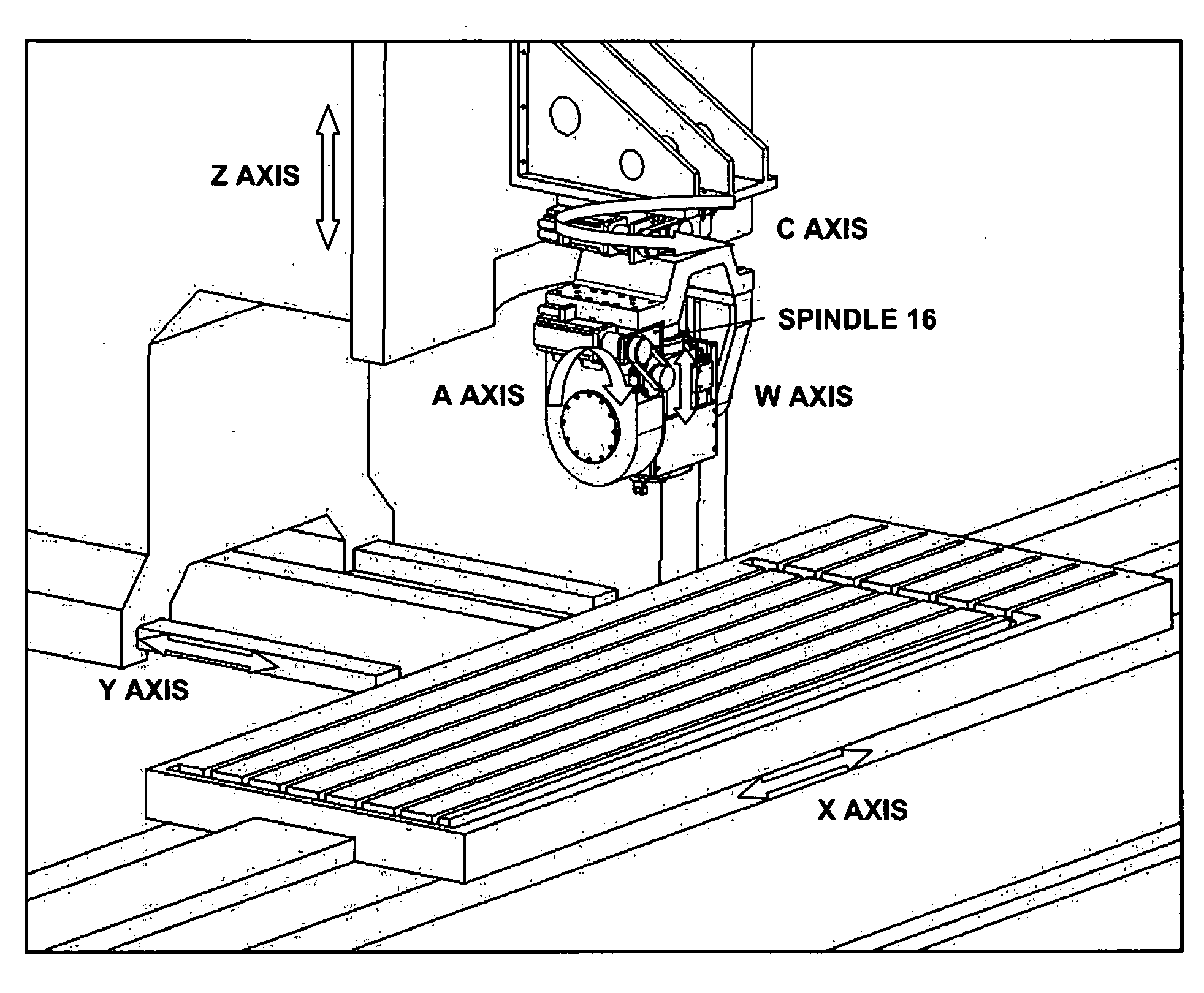
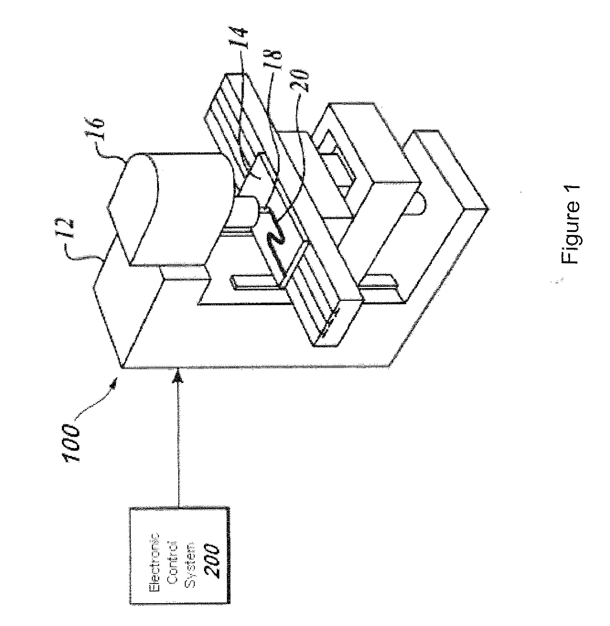
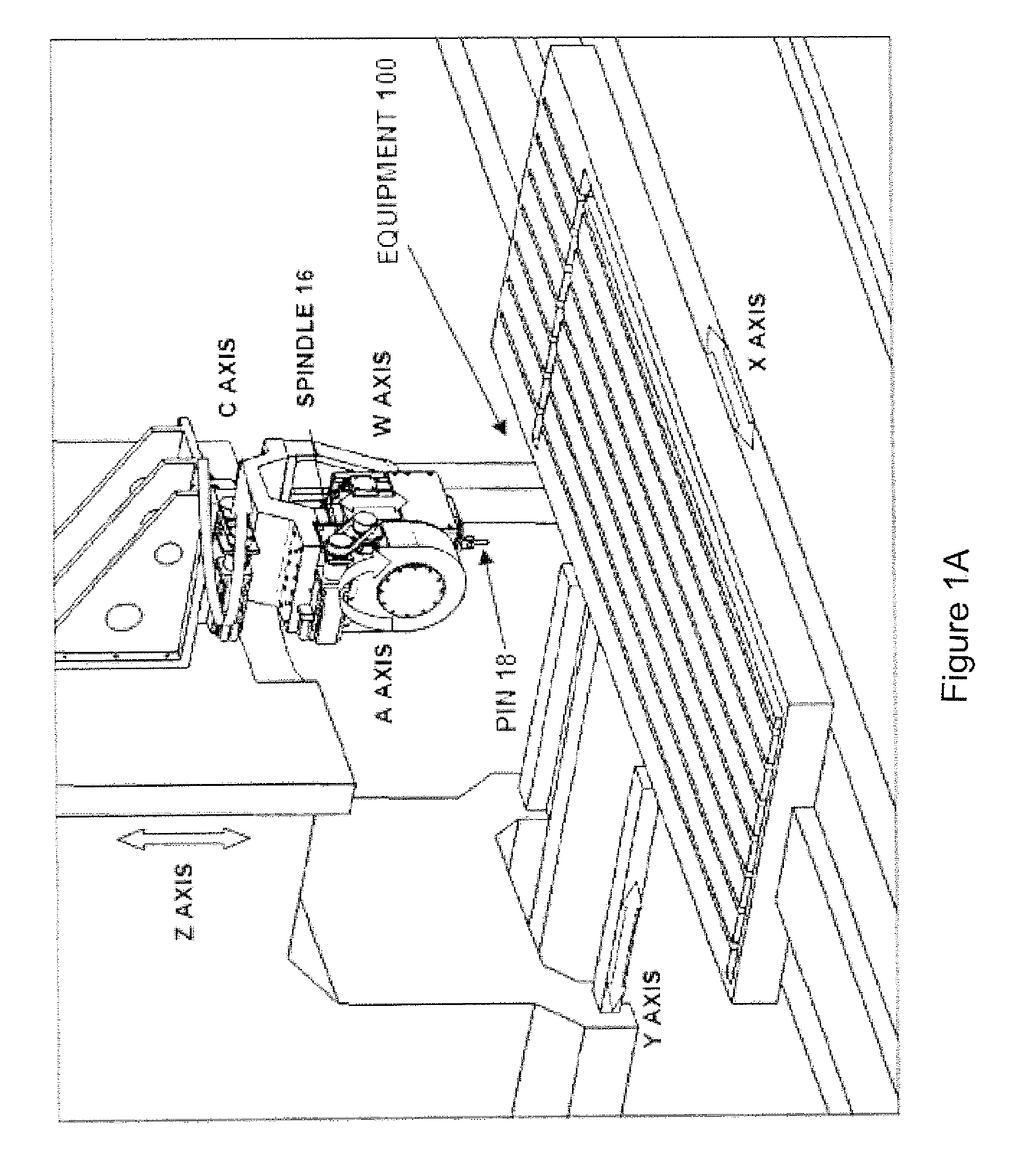
[0054]FIG. 1 is a side perspective view of exemplary illustrative non-limiting friction stir welding (FSW) equipment 100. Equipment 100 includes a frame 12 that moveably suspends a spindle 16 above a backing holding a workpiece 14. A rotating pin 18 replaceably installed in the spindle (this rotating pin is sometimes herein referred to as “the tool”) rotates in contact with the workpiece 14. By rotating in contact with the workpiece 14 with a desired amount of downforce, the rotating pin 18 accomplishes friction spin welding of the workpiece thereby for example welding two separate abutting pieces together along a weld line 20,

[0055]An electronic control system 200 controls the operation of equipment 100. In the exemplary illustrative non-limiting implementation, equipment 100 includes spindle 16 mounted in such a way that it can be controllable moved and positioned relative to the workpiece 14 clamped to or otherwise supported by the backing. The workpiece 14 typically comprises tw...


PUM

PropertyMeasurementUnit
axial distanceaaaaaaaaaa
threshold distanceaaaaaaaaaa
forceaaaaaaaaaa

Abstract

Friction stirred welding equipment, developed according to requirements of high reliability, robustness, precision and low cost, weld lap and butt joints in complex surfaces with fixed pin tool under controlled downforce. Exemplary equipment comprises a control force orbital spindle, wherein a coaxial sensor measures the downforce and simultaneously the axial electrical actuator corrects axial tool position along the welding, by a direct axial force system control, in order to maintain controlled downforce according to previously set parameters. The equipment sets up, monitors and controls the spindle rotation speed, welding speed, acceleration speed and downforce and can record in a database the downforce and tool welding position during the welding. The exemplary equipment may also comprise a laser system that scans the backing surface before welding and corrects original tool path, in order to provide an offset tool path and precision alarm system to get a safe welding, avoiding tool collision with the backing.

Description

CROSS-REFERENCES TO RELATED APPLICATIONS[0001]Not ApplicableSTATEMENT REGARDING FEDERALLY SPONSORED RESEARCH OR DEVELOPMENT[0002]Not ApplicableFIELD[0003]The technology herein generally relates to friction stir welding, and more specifically to a collection of techniques for controlling the force, axial position and other parameters of an orbital spindle used for friction stir welding. Still more specifically, the technology herein relates to an axial force system that monitors and controls the downforce of a friction stir welding orbital spindle by correcting axial tool position along the welding, e.g., according to numerical control parameters. The technology herein also includes a welding safety system that uses laser sensing to avoid tooling collision, and to other friction stir welding spindle control techniques.BACKGROUND AND SUMMARY[0004]Most people think of welding as requiring a torch or arc that is hot enough to melt the materials being welded. However, a kind of welding c...

Claims


Application Information

Patent Timeline
Patent Type & Authority Applications(United States)
IPC IPC(8): B23K20/12B23K20/26
CPCB23K20/123
Inventor CRUZ, MARCIO FERNANDOFROITAS, GUSTAVOZANINI, HAMILTONDA COSTA, JEFFERSON ADRIANOPEREITA, ROOSON FERNANDO DE OIVEIRAPEREIRA, EDSONFERNANDEZ, FERRANDO FERRERAANDENA, MAURICIO
Owner EMBRAER SA
Why Eureka
Try Eureka