Heat dissipation device

Inactive Publication Date: 2010-03-25
FU ZHUN PRECISION IND SHENZHEN +1
View PDF11 Cites 20 Cited by
  • Summary
  • Abstract
  • Description
  • Claims
  • Application Information

AI Technical Summary

Problems solved by technology

Computer electronic components, such as central processing units (CPUs), generate large amounts of heat during normal operation.
If the heat is not properly dissipated, it can adversely affect operational stability of the electronic components and damage associated electronic devices.
Due to a limited contacting area between the fins and the heat pipes, connection strength and reliability of the fins and the

Method used


Image

  • Heat dissipation device
  • Heat dissipation device
  • Heat dissipation device

Examples


Example

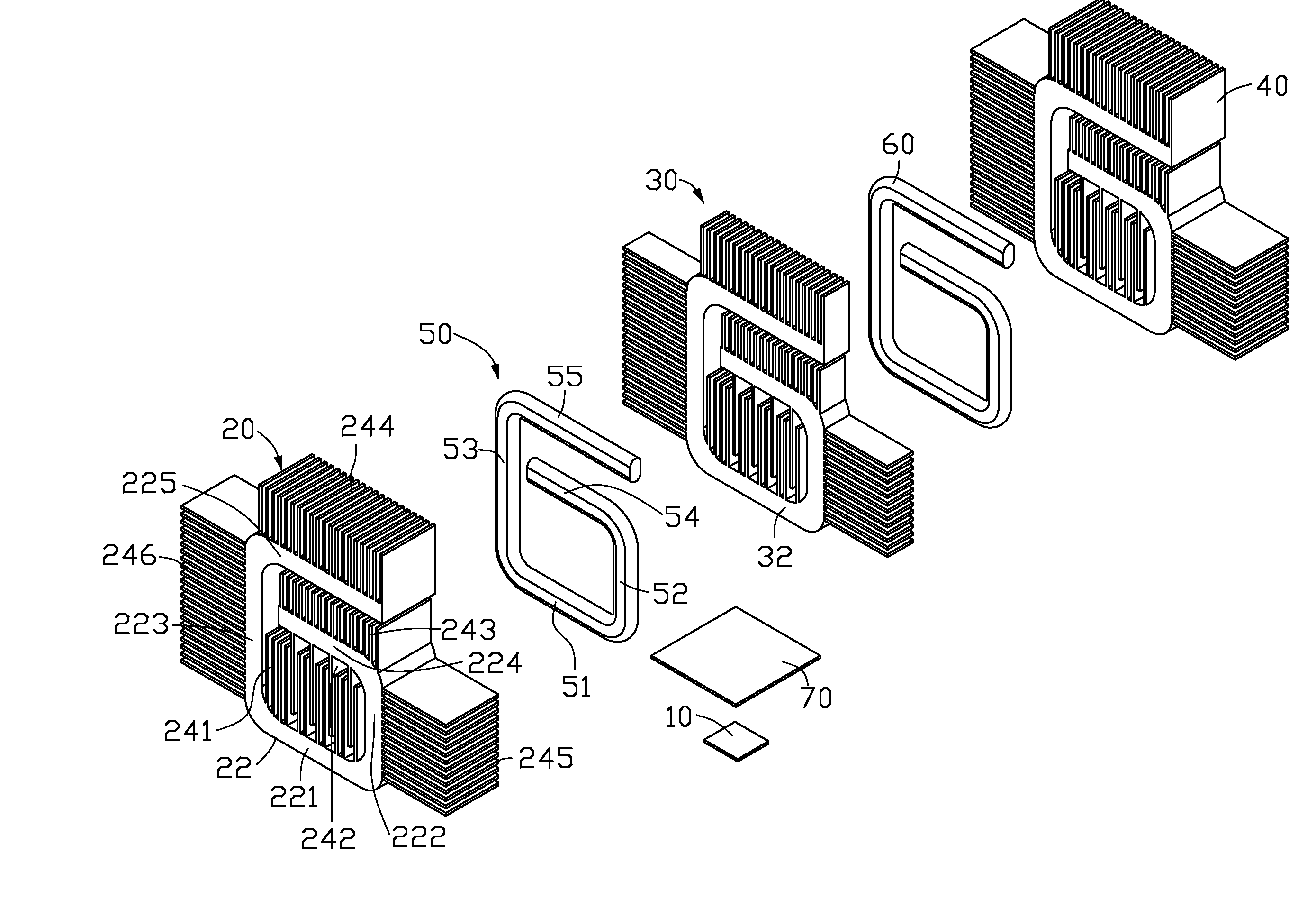
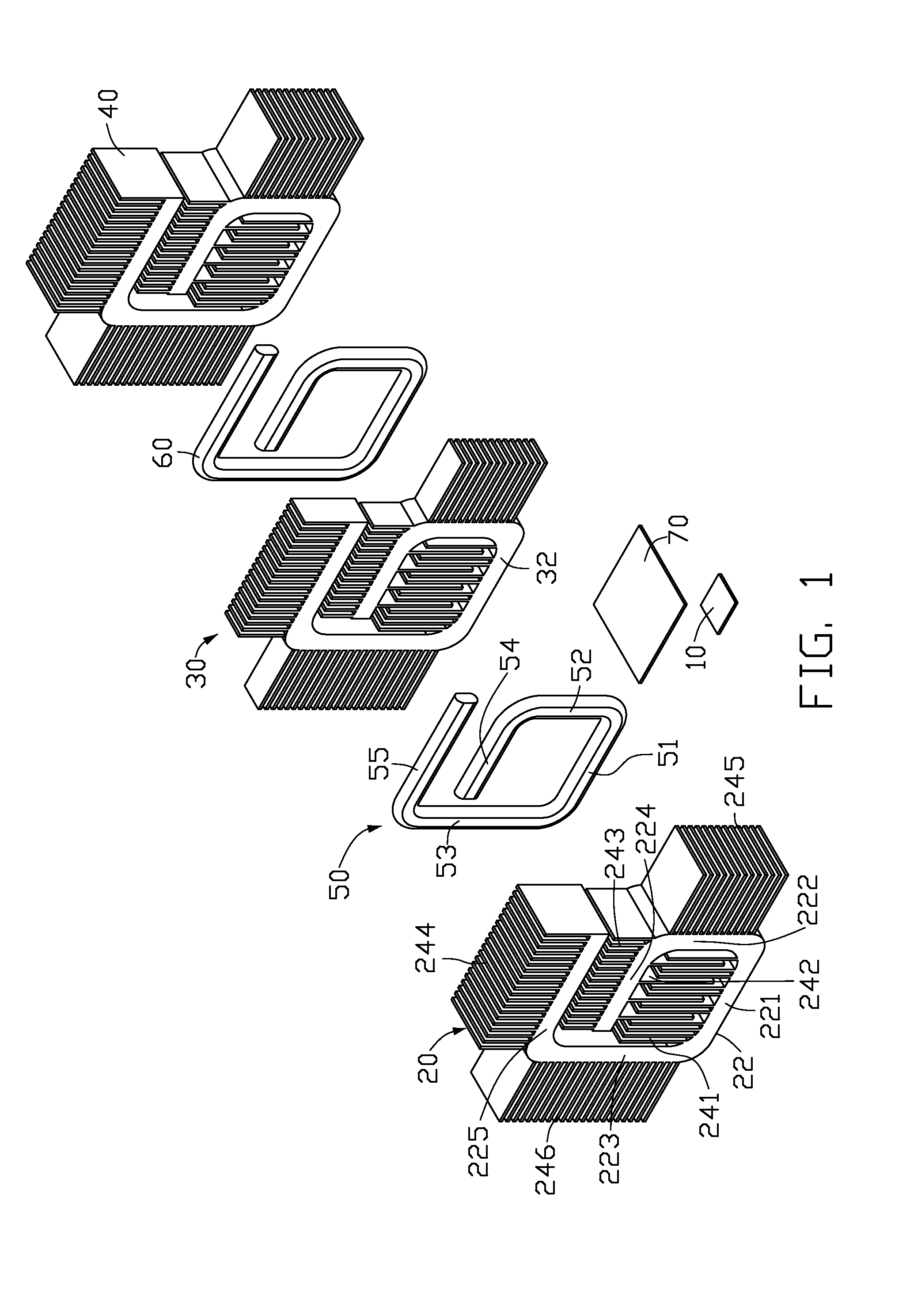
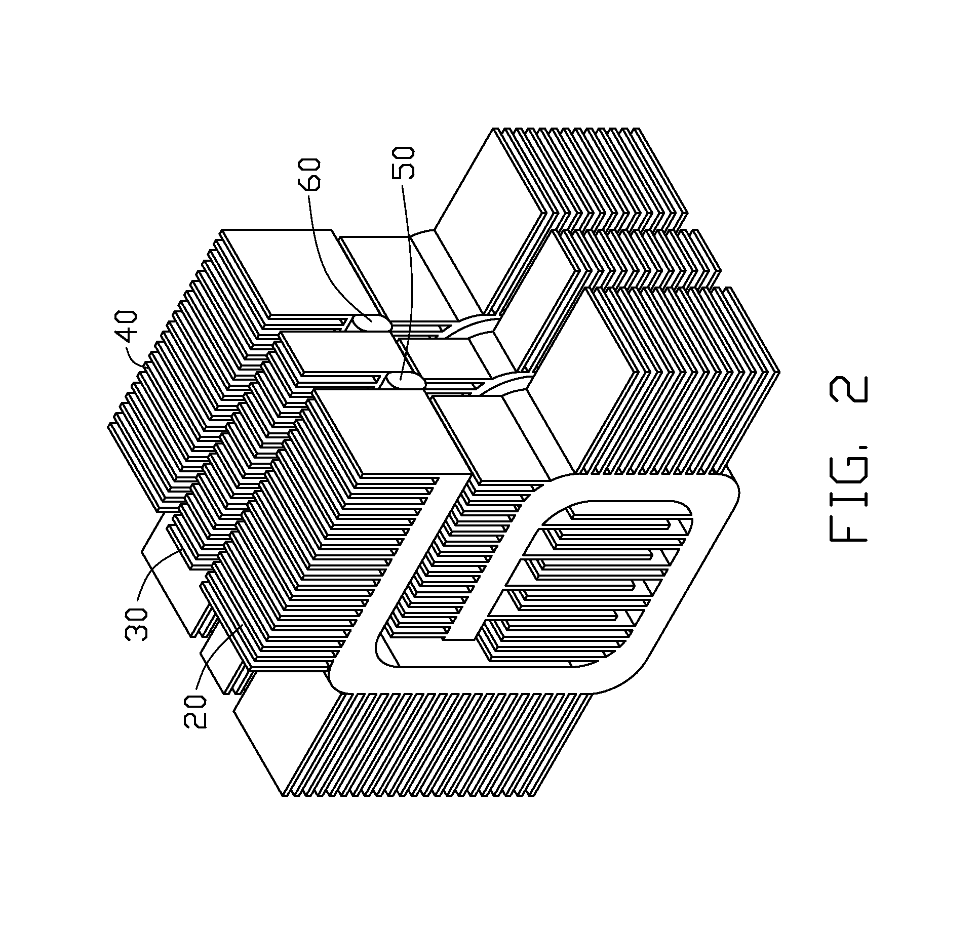
[0013]Referring to FIGS. 1-2, a heat dissipation device in accordance with a preferred embodiment is adapted to dissipate heat generated by an electronic component 10, such as a CPU. The heat dissipation device comprises a heat conducting plate 70 thermally contacting the electronic component 10, three heat sinks (i.e., a first heat sink 20, a second heat sink 30 and a third heat sink 40) and two heat pipes (i.e., a first heat pipes 50 and a second heat pipe 60) mounted on the heat conducting plate 70. The first heat pipe 50 is sandwiched between the first heat sink 20 and the second heat sink 30. The second heat pipe 60 is sandwiched between the second heat sink 30 and the third heat sink 40.

[0014]In the present embodiment, the first and second heat pipes 50, 60 are flattened, with an oval cross section; this means that contact surfaces of the heat pipes 50, 60 with the first, second and third heat sinks 20, 30, 40 are planar. Therefore, contact areas between the first and second h...


PUM


Abstract

A heat dissipation device includes two heat pipes, three extruded heat sinks and a heat conducting plate. Each heat pipe has a substantially G-shaped configuration and includes a heat absorbing section and first and second heat dissipating sections. The first and second heat dissipating sections extend along opposite directions, wherein the second heat dissipating section is located above the first heat dissipating section. Each heat sink includes a main body and a plurality of fins extending from the main body. The main body of each heat sink has a same profile with that of each heat pipe. Each heat pipe is sandwiched between the main bodies of two adjacent heat sinks. The heat conducting plate is attached to the main bodies of the heat sinks and the heat absorbing sections of the heat pipes.

Description

BACKGROUND OF THE INVENTION[0001]1. Field of the Invention[0002]The present invention relates to a heat dissipation device used in association with electronic components.[0003]2. Description of Related Art[0004]Computer electronic components, such as central processing units (CPUs), generate large amounts of heat during normal operation. If the heat is not properly dissipated, it can adversely affect operational stability of the electronic components and damage associated electronic devices. A heat dissipation device is often attached to a top surface of an electronic component to dissipate heat therefrom.[0005]Conventionally, the heat dissipation device includes a base, a plurality of fins arranged on the base, and a plurality of heat pipes connecting the base and the fins. A plurality of grooves is defined in the base, and a plurality of holes is defined in the fins. Each heat pipe has a bent configuration and includes an evaporating section received in a corresponding groove of t...

Claims


Application Information

Patent Timeline
IPC IPC(8): H05K7/20
CPCF28D15/0266F28F1/32H01L23/427H01L23/467H01L2924/0002F28D15/0275H01L2924/00
Inventor LIU, PENG
Owner FU ZHUN PRECISION IND SHENZHEN
Why Eureka
Try Eureka