Lamp and use thereof

a technology of lamps and light sources, applied in the field of lamps, can solve the problems of less defined direction of emitted light, and achieve the effect of enhancing the brightness of the lamp and broadening the range of effects availabl

Inactive Publication Date: 2010-03-25
SIGNIFY HLDG BV
View PDF7 Cites 15 Cited by
  • Summary
  • Abstract
  • Description
  • Claims
  • Application Information

AI Technical Summary

Benefits of technology

[0026]In a particular embodiment, the lightguide comprises parallel first and second lightguide parts. This further broadens the gamut of effects obtainable. E.g., the lightguide parts may be provided side-by-side, with different extraction structures, or may be lying on different curves / lines. It is also possible to provide the lightguide parts so as to be overlapping, i.e. having at least partly overlapping respective front surfaces. In such a case, virtual images as created by the lightguide parts may also be overlapping. E.g., in an advantageous embodiment, the lamp further comprises two arrays of light sources, and respective light receiving sides of the first and second lightguide parts are optically connected to one of the two arrays of light sources.
[0027]In a particular embodiment, the two arrays of light sources are arranged on different, preferably opposite, sides of the lamp. This may simply be used to enhance the brightness of the lamp, but also to add various effects in one lamp.

Problems solved by technology

However, a disadvantage of such backlights, or lamps of this kind in general, is that the direction of the emitted light is much less well-defined.

Method used


Image

  • Lamp and use thereof
  • Lamp and use thereof
  • Lamp and use thereof

Examples


Embodiment Construction

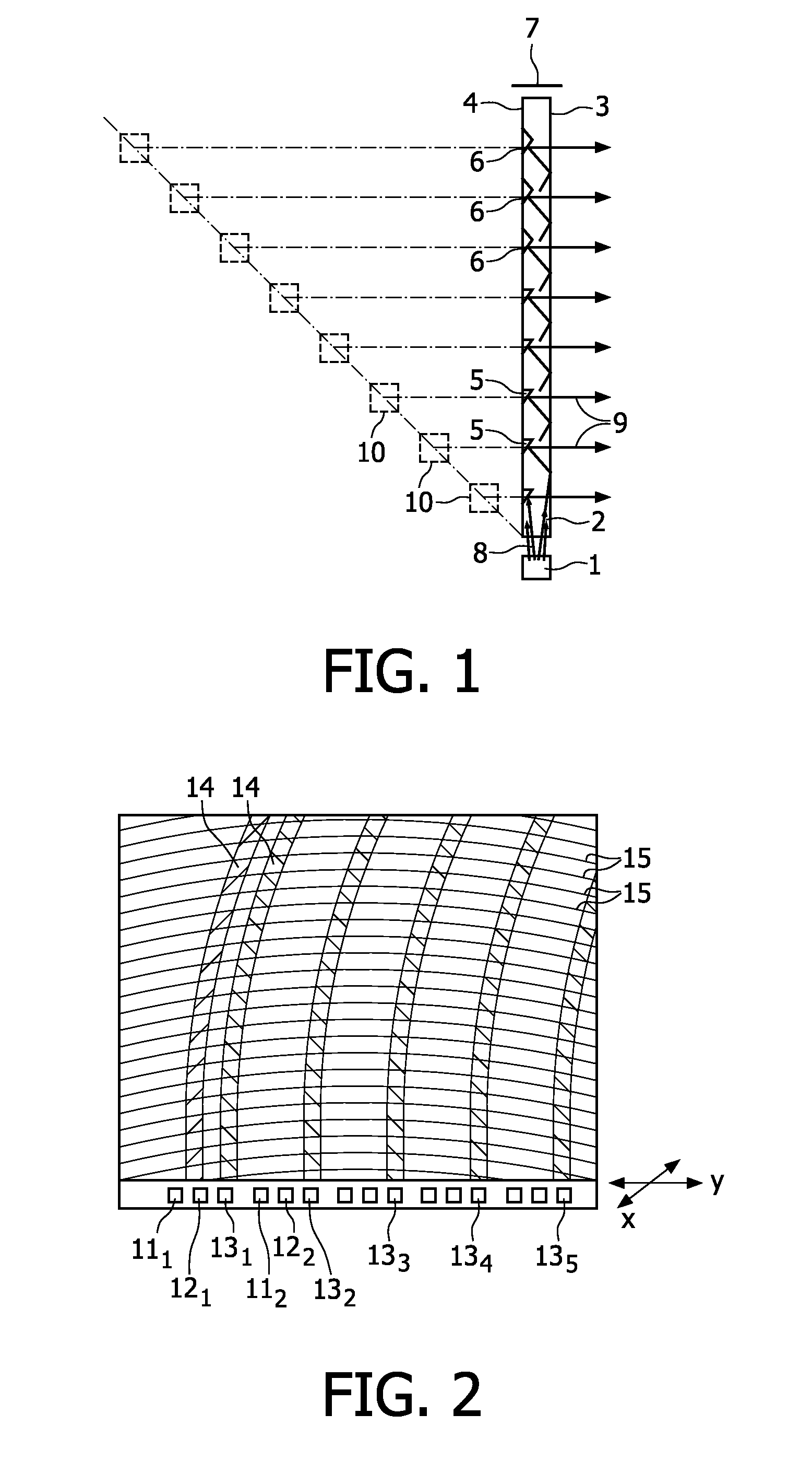
[0047]FIG. 1 very diagrammatically shows a lamp according to the invention, in a cross-sectional side view, with a 3D appearance.

[0048]Herein, 1 denotes an LED and 2 a lightguide with a front surface 3 and a back surface 4. In the lightguide there are a plurality of extraction structures 5 and 6. A mirror is denoted with reference numeral 7.

[0049]LED 1 emits a (narrow) bundle of light 8 that enters the lightguide 2. The light is guided by total internal reflection at the front surface 3 and the back surface 4. If necessary, the light is reflected back by mirror 7.

[0050]A part of the light will be incident on the extraction structures 5, either directly or after a number of reflections, as partly indicated by dashed lines. The extraction structures 5 are recesses that are e.g. machined into the lightguide, and that comprise a reflection surface at an angle e.g. between 30 and 50°. The light that is incident on the extraction surfaces is reflected to the front surface 3 and is able to...


PUM


Abstract

A lamp for emitting light, comprising a transparent sheet-like lightguide, with at least one light receiving side, a light emission front surface and a back surface opposite the front surface. The lamp further comprises a plurality of light sources, positioned in an array and optically coupled to at least one light receiving side. The back surface of said lamp comprises a plurality of optical extraction structures, for example provided in parallel curved lines. Furthermore, the lamp is substantially free from light scattering structures in a light path of the light to be emitted.

Description

FIELD OF THE INVENTION[0001]The invention relates in general to a lamp. In particular, the invention relates in a first aspect to a lamp for emitting light, comprising a transparent sheet-like lightguide, with at least one light receiving side, a light emission front surface and a back surface opposite the front surface, and a plurality of light sources, positioned in a linear array and adjacent at least one light receiving side, wherein the back surface comprises a plurality of reflective optical extraction structures.BACKGROUND OF THE INVENTION[0002]So-called backlights of e.g. liquid crystal displays generally have a similar construction, comprising a side-lit lightguide, and extraction features to extract the light out of the lightguide. Such backlights may e.g. be relatively flat lamps that still have a large light emitting area. Often, these backlights have to fulfill the requirement of providing lighting as homogeneously as possible, and in particular the light extraction str...

Claims


Application Information

Patent Timeline
Patent Type & Authority Applications(United States)
IPC IPC(8): G02B6/04F21V1/00F21V9/00
CPCG02B6/0068G02B6/0038
Inventor CORNELISSEN, HUGO JOHANVAN DELDEN, MARTINUS HERMANUS WILHELMUS MARIA
Owner SIGNIFY HLDG BV
Why Eureka
Try Eureka