Method and System for Energy Returning Ankle Foot Orthosis (ERAFO)

a technology of energy-returning ankle feet and orthotics, applied in the field of orthotics, can solve the problems of not taking advantage of potentially excess mechanical energy, device not delivering energy in a manner, limited utility of this design, etc., to improve walking efficiency, enhance walking performance, and improve the effect of weak power

Inactive Publication Date: 2010-03-25
UNIV OF VIRGINIA ALUMNI PATENTS FOUND
View PDF6 Cites 13 Cited by
  • Summary
  • Abstract
  • Description
  • Claims
  • Application Information

AI Technical Summary

Benefits of technology

[0015]In one embodiment, two cantilever springs (e.g., spring mechanism or any energy storage device/system or the like) beneath the foot that are linked through cables and controlled by one or more ratchets. As the rear cantilever spring is depressed to store energy, the front spring is elevated until forefoot pressure depresses it, later in the gait cycle, to trigger the release of the energy stored in the rear spring. Or said differently, the rear cantilever is depressed with foot contact to store energy until the elevated front beam depresses as the body weight transitions forward during gait thus releasing the energy stored in the rear beam. While this brace is helpful to augment the weak power found in patients with CP, the mechanics of the brace are used to enhance walking performance in other medical conditions and potentially even in persons without specific disabilities.
[0016]The various embodiments of the present inv

Problems solved by technology

While these devices may possibly aid the subject with certain motions to and restrict undesired movements, they do not take advantage of potentially excess mechanical energy which can be used to aid the subject's movements.
As discussed in the article, the utility of this design is limited by its size and complexity.
Finally, this device does not deliver the energy in a manner that aids the subject in propelling herself—it merely helps her develop adequate foot-ground clearance.
In the specific case of ankle foot orthoses (AFOs), many prior art devices only provide subjects with small improvements in walking capability.
Thus a stiffer brace restricts ankle motion and the ability of the ankle to apply walking force, while a more flexible brace may not provide sufficient support or be able to store sufficient energy to improve walking.
There is typically an external plantar flexor moment because initial floor co

Method used


Image

  • Method and System for Energy Returning Ankle Foot Orthosis (ERAFO)
  • Method and System for Energy Returning Ankle Foot Orthosis (ERAFO)
  • Method and System for Energy Returning Ankle Foot Orthosis (ERAFO)

Examples


Embodiment Construction

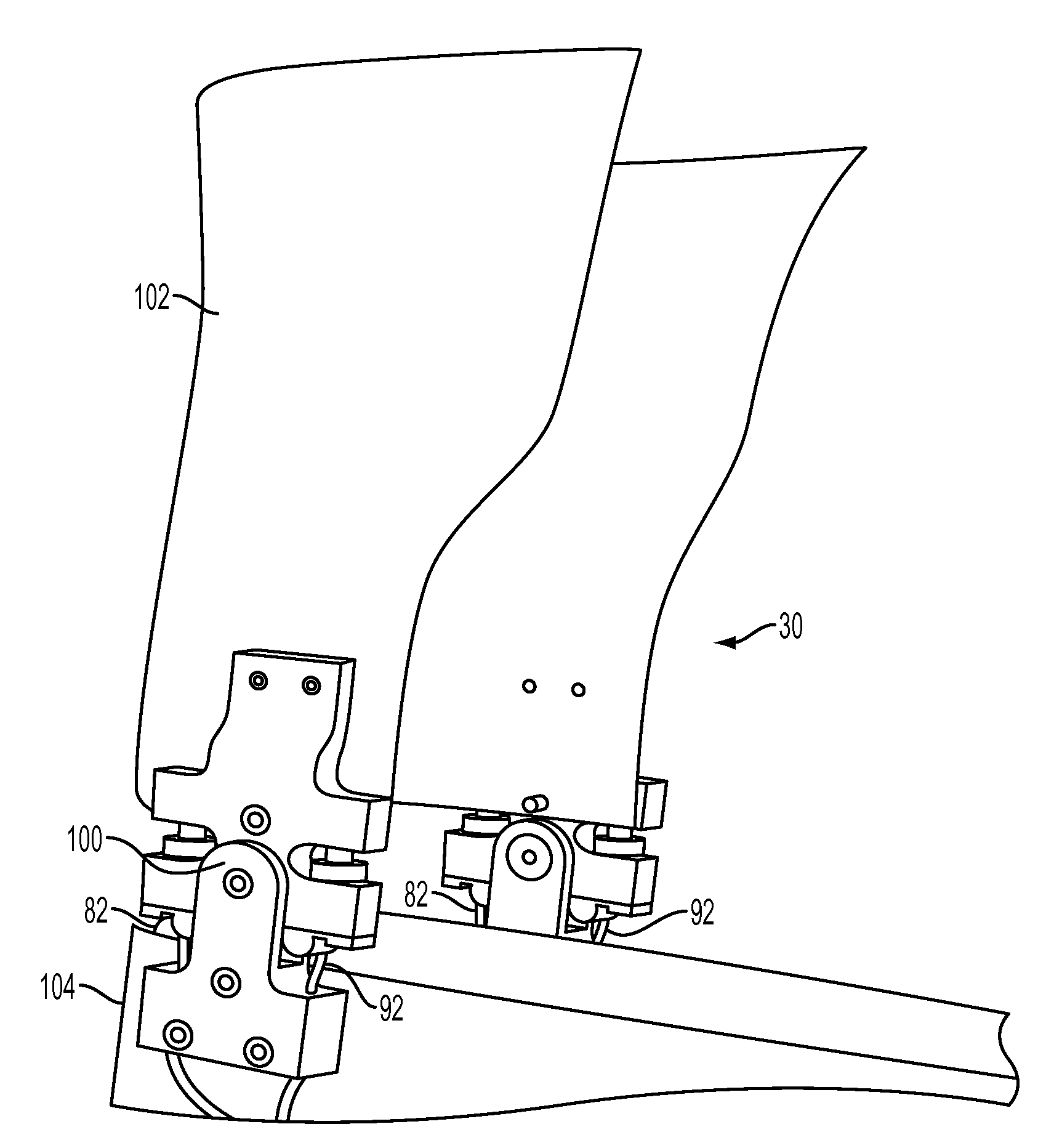
[0030]The exemplary embodiments described herein relate to orthotic devices and methods, for example and without limitation, to an ankle foot orthosis (AFO). It will be apparent to those of ordinary skill in the art that the devices and processes disclosed herein may be useful for other types of orthotic devices which serve as supports or braces for weak or ineffective joints or muscles, or which assist amputees or non-impaired subjects with one or more movements.

[0031]In order to more clearly and concisely describe the subject matter of the claims, the following definitions are intended to provide guidance as to the meaning of specific terms used in the following written description, examples, and appended claims.

[0032]As used herein, the term “extremity” includes a limb of the body, particularly a human hand or foot; or any body part / location as applied in desired or required operation of the present invention device and method.

[0033]As used herein, the term “locomotion” means the...


PUM


Abstract

An orthotic device/system and method including at least one energy storage component and at least one trigger component which prevents release of the stored energy until the desired point in the movement cycle of an extremity. Use of the device/system and method permits, among other things, the orthosis to capture energy from the force present between a patient and a supporting surface and return it at a specified point in the movement cycle of the subject's extremity.

Description

CROSS-REFERENCE TO RELATED APPLICATION[0001]This application claims the benefit of priority of U.S. Provisional Application Ser. No. 60 / 695,346, filed on Jun. 30, 2005, entitled “Method And System For Energy Returning Ankle Foot Orthosis (ERAFO),” of which is hereby incorporated by reference herein in its entirety.FIELD OF THE INVENTION[0002]The present invention relates generally to orthotic devices, and, more particularly, to orthotic devices which capture and return mechanical energy to assist the subject with certain motions.BACKGROUND OF THE INVENTION[0003]Orthotic devices are typically prescribed to serve as supports or braces for weak or ineffective joints or muscles. Some conventional orthoses allow limited motion of one or more of a subject's joints, often in one plane, by connecting the rigid portions of the orthosis with hinges or incorporating a flexible member which is capable of being bent as the subject moves.[0004]More advanced conventional orthoses utilize various e...

Claims


Application Information

Patent Timeline
IPC IPC(8): A61B5/103A61H1/02
CPCA61F5/0127A61F5/0102
Inventor ABEL, MARK F.ALLAIRE, PAUL E.BENNETT, BRADFORD C.WOLOVICK, ADAM C.
Owner UNIV OF VIRGINIA ALUMNI PATENTS FOUND
Why Eureka
Try Eureka