Spinous process spacer implant and technique

a technology of spacer and spacer body, applied in the field of spinal stenosis treatment devices and methods, can solve the problems of non-biological, multi-piece design, wear and implantation complexity, and the device's expansive geometry may not lend itself to minimally invasive surgical techniques,

Inactive Publication Date: 2010-03-25
EVOLUTION SPINE TECH
View PDF29 Cites 65 Cited by
  • Summary
  • Abstract
  • Description
  • Claims
  • Application Information

AI Technical Summary

Benefits of technology

[0010]A spinous process spacer device for surgical implantation between the spinous processes of adjacent upper and lower vertebrae is disclosed. The spacer device maintains a desired space between the adjacent spinous processes. It comprises a tubular member having an axis, a length, an axial lumen coextensive with the length, an outer diameter, an upper end and a lower end. The upper and lower ends each have a pair of diametrically opposed notches (cut outs) along the outer diameter of the spacer device. The pair of diametrically opposed notches in the upper end is aligned with the pair of diametrically opposed notches in the lower end. When properly positioned, the pairs of diametrically opposed notches are dimensioned to receive a portion of the spinous processes, thereby maintaining the desired space between adjacent spinal processes.

Problems solved by technology

While this in itself does not necessarily cause symptoms, swelling and nerve inflammation results when the narrowing leads to compression of the spinal cord and nerve roots.
While surgical options are available, they are invasive.
Due to the inherent risks involved with such procedures, surgery is usually considered only after other non-invasive procedures have failed.
Although the Zucherman device achieves spinal distraction, it nonetheless presents some limitations.
It is a non-biological, multi-piece design, subject to wear and implantation complexity.
Furthermore, the expansive geometry of the device may not lend itself to minimally invasive surgical techniques seeking to conserve muscle mass and soft tissue in the regions adjacent the spinous processes.

Method used


Image

  • Spinous process spacer implant and technique
  • Spinous process spacer implant and technique
  • Spinous process spacer implant and technique

Examples


Embodiment Construction

[0061]The term “allograft”, as used herein, is intended to mean a graft taken from a different individual of the same species.

[0062]The term “sagittal plane”, as used herein, is the plane which splits the body into left and right segments. The mid-sagittal, or median plane splits the body into equal left and right halves.

[0063]The term “coronal plane”, as used herein, is the plane that separates the body into anterior and posterior (front and back) segments. The coronal plane is perpendicular to the sagittal plane.

[0064]The term “posterior process fusion”, as used herein, describes the fusion of adjacent spinous processes firstly to the spinous process spacer implant, and eventually to each other via the growth of tissue through the axial conduit of the implant.

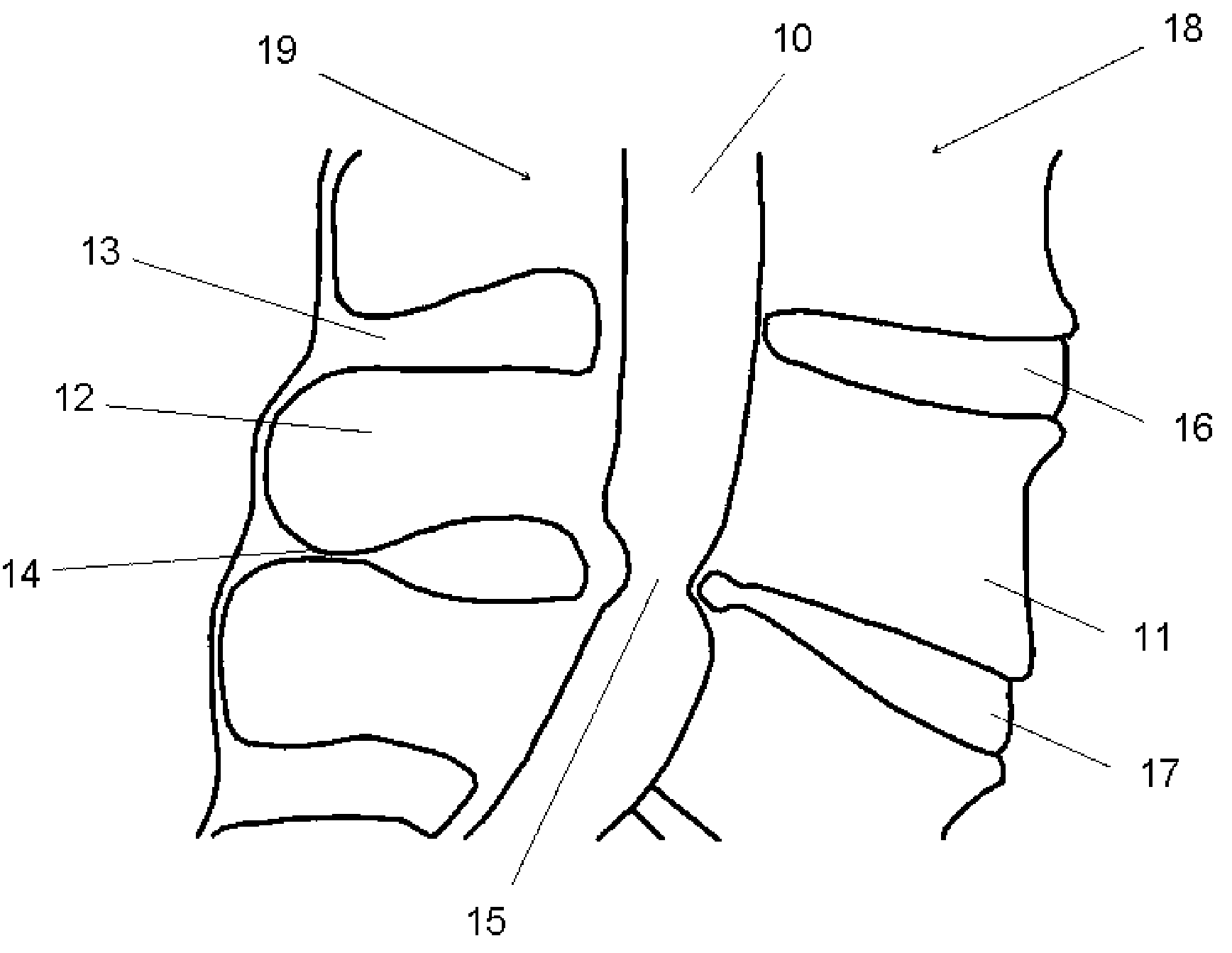
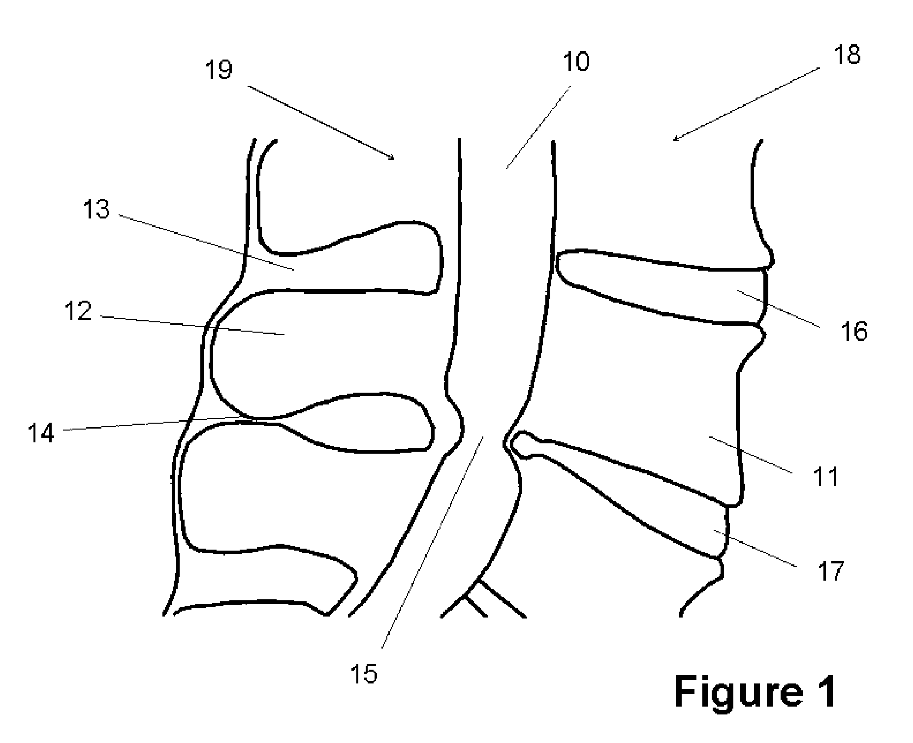
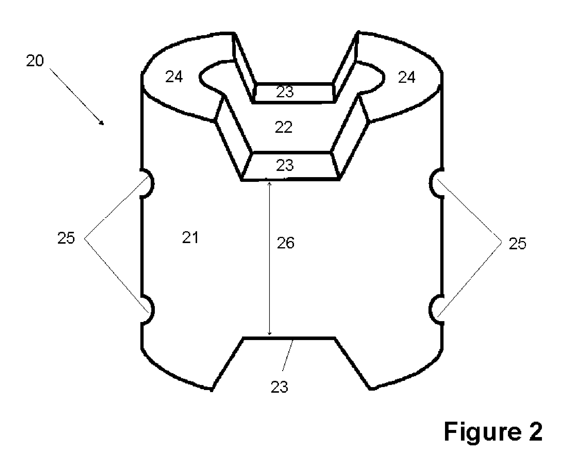
[0065]The function of the spinous process spacer (20) can be understood by appreciating the problem illustrated in FIG. 1. A cross section of the spinal cord (10) in the mid-sagittal plane is shown with the vertebral body (11...


PUM


Abstract

A spinous process spacer implant and method of use are provided. The implant can be configured to be placed between adjacent spinous processes. The implant can comprise at least one pair of notches that can be positioned such that portions of the adjacent spinous processes are engaged therewithin to maintain a size of a desired space between the adjacent spinous processes.

Description

CROSS-REFERENCE TO RELATED APPLICATIONS[0001]This application is a divisional of U.S. application Ser. No. 11 / 308,767, filed May 1, 2006, which claims the benefit of U.S. Provisional Application No. 60 / 676,538, filed on May 2, 2005, the entireties of each of which are hereby incorporated herein by reference.BACKGROUND[0002]1. Field of the Inventions[0003]This invention generally relates to a device and method for the treatment of spinal stenosis.[0004]2. Description of the Related Art[0005]Spinal stenosis is a narrowing of the spinal canal. While this in itself does not necessarily cause symptoms, swelling and nerve inflammation results when the narrowing leads to compression of the spinal cord and nerve roots.[0006]While spinal stenosis can be found in any part of the spine, the lumbar and cervical areas are most commonly affected. Patients with lumber spinal stenosis may feel pain, weakness, or numbness in the lower extremities. Symptoms often increase when walking short distances...

Claims


Application Information

Patent Timeline
Patent Type & Authority Applications(United States)
IPC IPC(8): A61B17/88
CPCA61B17/7062
Inventor WARNER, KENNETH D.GOLDSTEIN, STEVEN B.
Owner EVOLUTION SPINE TECH
Why Eureka
Try Eureka