
Memory Management Method, Memory Management Apparatus, and Recording Medium Recording the Memory Management Program

Inactive Publication Date: 2010-03-25
KYOTO UNIV
View PDF4 Cites 6 Cited by
  • Summary
  • Abstract
  • Description
  • Claims
  • Application Information

AI Technical Summary

Benefits of technology

[0014]According to such a configuration, when or after the main program writes the data into the recording area of the copy source object or the recording area of the copy destination object, the data to execute the writing can be written into both the recording areas of the copy source object and the copy destination object. Consequently, data consistency can be ensured between the copy source object and the copy destination object and the process of generating the continuous available area can thereby be interrupted to make the main program execute the process. Consequently, the continuous available area can be generated in the heap area without reducing real time effectiveness in the process of the main program.
[0026]According to such a configuration, the data recording area including the stack area is allocated in the heap area, and the area in the heap area in which the data recording area is not included is determined to be the heap area described in one of claims 1 to 3, so that the effect similar to the invention described in one of claim 4 can be obtained. Moreover, the process of moving the stack area in the limited area to the available area in the heap area can be interrupted to make the main program execute the process. Consequently, the stack area in the limited area can be moved to the available area in the heap area without reducing real time effectiveness of the main program.

Problems solved by technology

As a result, real time effectiveness of the main program is reduced.
However, in the above invention, the compaction process to generate the continuous available area cannot be interrupted, and the main program cannot execute the process until the compaction process is completed.
As a result, the process of the memory management program cannot be interrupted, so that the execution of the main program is often interrupted for milliseconds to seconds.
However, a timing for executing the memory management program mandatorily is often different due to differences in a process which requires real time effectiveness, a size of a memory area which varies according a type of mobile phone, and a processing speed of the main program.
As a result, a developer needs to set up the timing for executing the memory management program mandatorily in view of the differences, so that a time and effort is required for the development and the development is not efficiently promoted.
However, as for the above compaction process, the whole process of updating the referential destinations of all the pointers which refer to the move source after moving the data needs to be executed together, so that the compaction process cannot be interrupted to execute the main program.
As a result, real time effectiveness of the main program is reduced.
However, in the same manner as the non-patent document 1, this process does not also enable the interruption of the compaction process to execute the main program, so that real time effectiveness of the main program is reduced.
Moreover, as for this process, the move destination area of the data needs to be set up before the main program records the data in the memory area, so that the move destination area cannot be set up in view of a state of recording the data in the memory area, and so on, and the available area cannot be generated efficiently.
Accordingly, when adding a particular process to the readout process of the data, overhead increases during the readout of the data, and execution efficiency of the main program often reduces.
However, also in this process, the overhead increases during the readout of the data, and the execution efficiency of the main program often reduces.

Method used


Image

  • Memory Management Method, Memory Management Apparatus, and Recording Medium Recording the Memory Management Program
  • Memory Management Method, Memory Management Apparatus, and Recording Medium Recording the Memory Management Program
  • Memory Management Method, Memory Management Apparatus, and Recording Medium Recording the Memory Management Program

Examples


Embodiment Construction

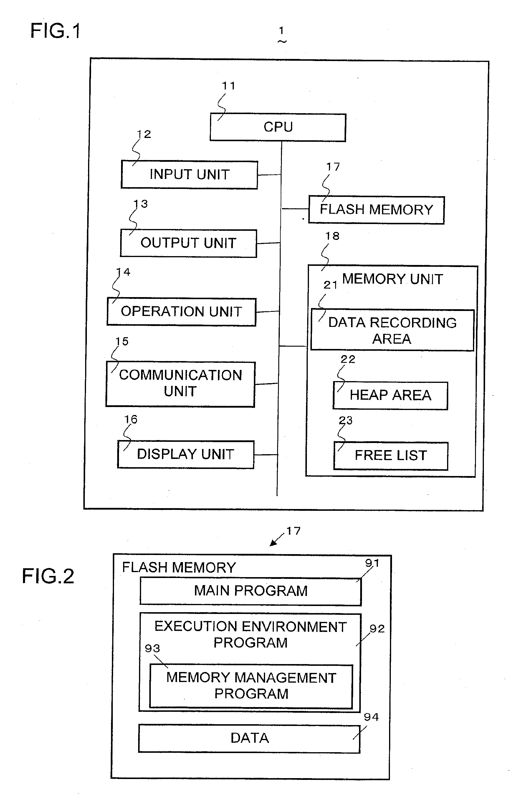
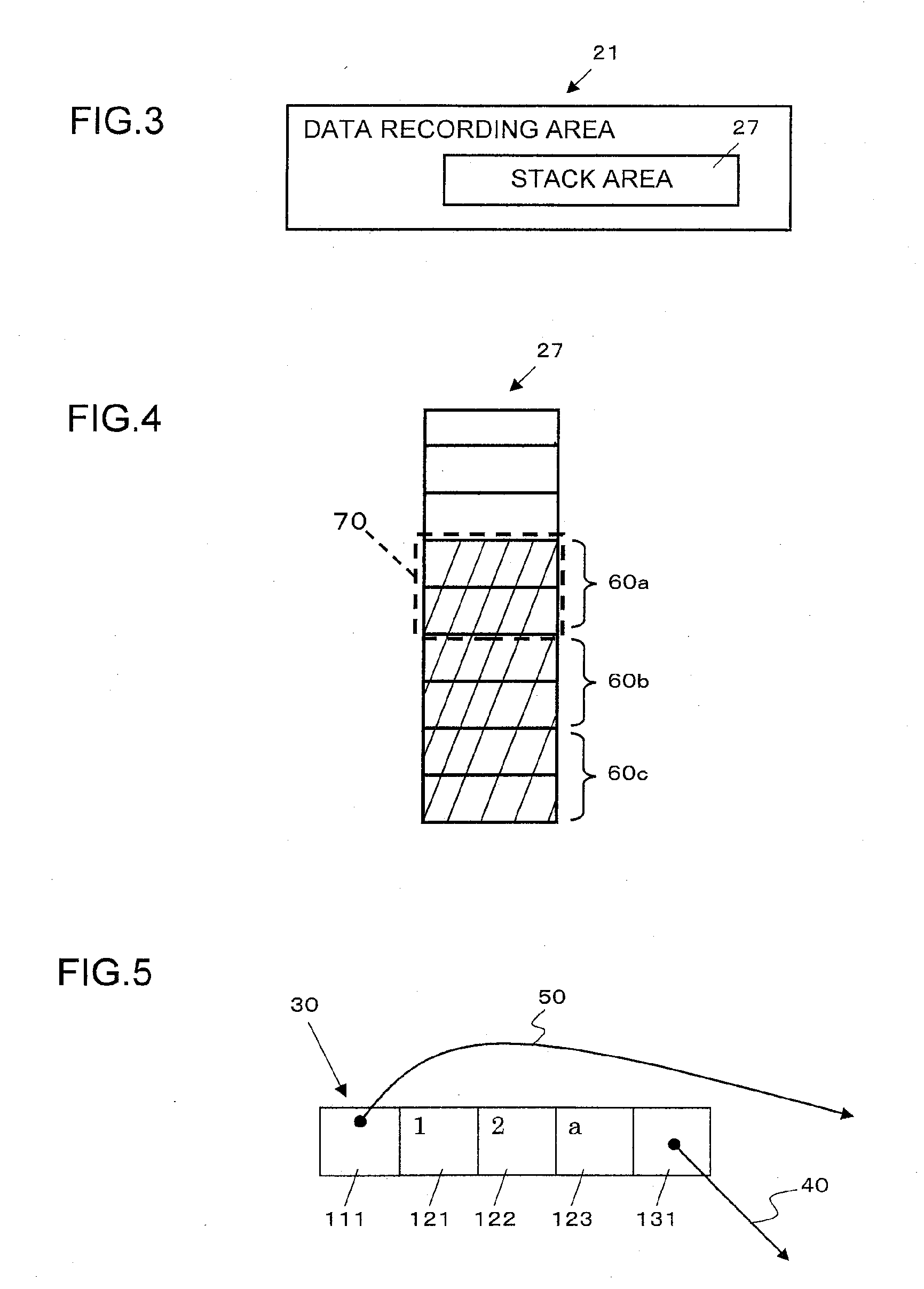
[0058]A mobile phone (a memory management apparatus) according to the first preferred embodiment of the present invention is described with reference to the drawings. The following preferred embodiment describes a case that the memory management apparatus of the present invention is applied to the mobile phone. FIG. 1 shows a configuration of a mobile phone 1, FIG. 2 shows a configuration of a flash memory (a recording medium) 17, and FIG. 3 shows a configuration of a data recording area 21. The mobile phone 1 can execute a program 91 which is created using Java language to generate a dynamic data (abbreviated as the main program 91 hereinafter) and a memory management program 93 of the present invention.

[0059]The mobile phone 1 includes an input unit 12 such as a microphone to input an audio, an output unit 13 such as a speaker to output an audio, an operation unit 14 which has keys operated by a user, a communication unit 15 which sends and receives an audio data and so on, and a ...


PUM


Abstract

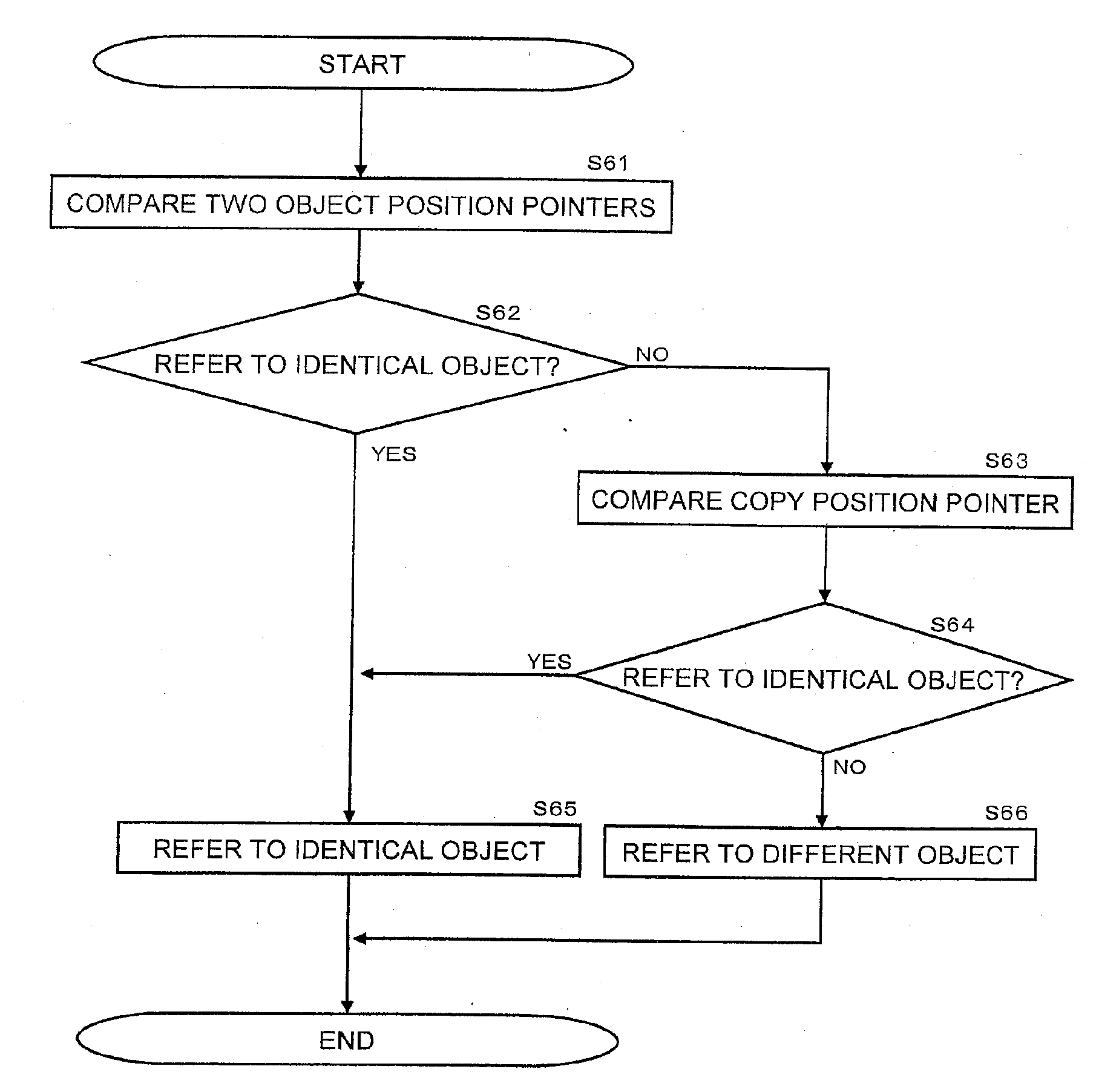
In a memory management method, a memory management device, and a recording medium containing a memory management program, a main program executes a process by interrupting a process for generating a continuous usable region. When the main program writes data into a heap region during a compaction process, the memory management program judges whether the data write destination is a recording region of the object to be copied or a recording region of the copied object. If the data write destination is one of those recording regions, then the write data is written into both the recording regions of the object to be copied and the copied object. For this, even if the main program performs writing during a compaction process, it is possible to maintain consistency between data on the object to be copied and the copied object.

Description

TECHNICAL FIELD[0001]The present invention relates to a memory management method, a memory management apparatus, and a recording medium which records a memory management program.BACKGROUND ART[0002]A program which is created using a programming language to generate a dynamic data such as Java language (abbreviated as the main program hereinafter) records the generated data in a memory area dynamically, so that a free area which the main program can use (abbreviated as the available area hereinafter) becomes insufficient unless the data, which becomes unnecessary as the execution of the main program progresses, is deleted. Consequently, there is a known method for deleting the unnecessary data in the memory area and reusing the memory area conventionally.[0003]A process of deleting the unnecessary data in the memory area to reuse the area is called as garbage collection (abbreviated as the GC hereinafter). A process of collecting the available area which becomes reusable by the GC pr...

Claims


Application Information

Patent Timeline
IPC IPC(8): G06F12/16G06F12/00
CPCG06F12/0269
Inventor UGAWA, TOMOHARUYUASA, TAIICHI
Owner KYOTO UNIV
Learn More