Header ground sensor

a header and ground sensor technology, applied in harvesters, applications, picking devices, etc., can solve the problems of short straight ground sensor mounted close to the cutter bar, short straight ground sensor risked breakage, short straight ground sensor could also be broken, etc., to reduce the likelihood of damage

Inactive Publication Date: 2010-04-01
CLAAS SELBSTFAHRENDE ERNTEMASCHINEN GMBH
View PDF48 Cites 17 Cited by
  • Summary
  • Abstract
  • Description
  • Claims
  • Application Information

AI Technical Summary

Benefits of technology

[0011]One aspect of the invention combines a short ground sensor arm mounted close to the cutter bar and a longer rod mounted towards the rear of the header in a direction of travel. The short front sensor and long rear sensor are connected by a linkage which translates motions from either sensor to the other sensor. A second linkage translates the motions of either sensor rearward to a protected area under the heade

Problems solved by technology

Thus, long ground sensor arms did not work well for short cutting heights.
Moreover, a short straight ground sensor mounted close to the cutter bar risked breakage when the operator

Method used


Image

  • Header ground sensor
  • Header ground sensor
  • Header ground sensor

Examples


Embodiment Construction

[0022]The following description of the preferred embodiment(s) is merely exemplary in nature and is in no way intended to limit the invention, its application, or uses.

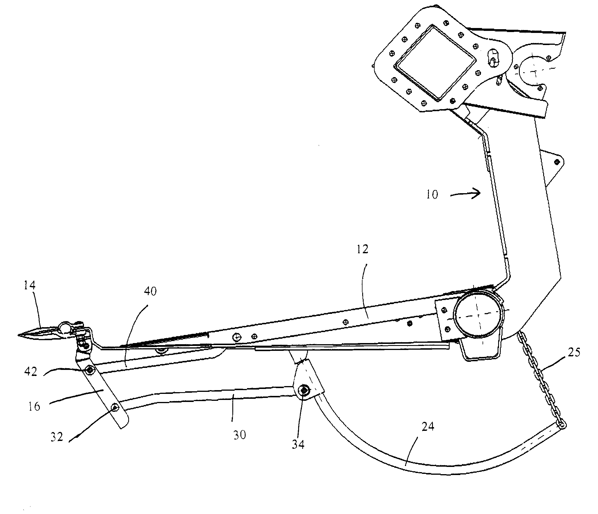
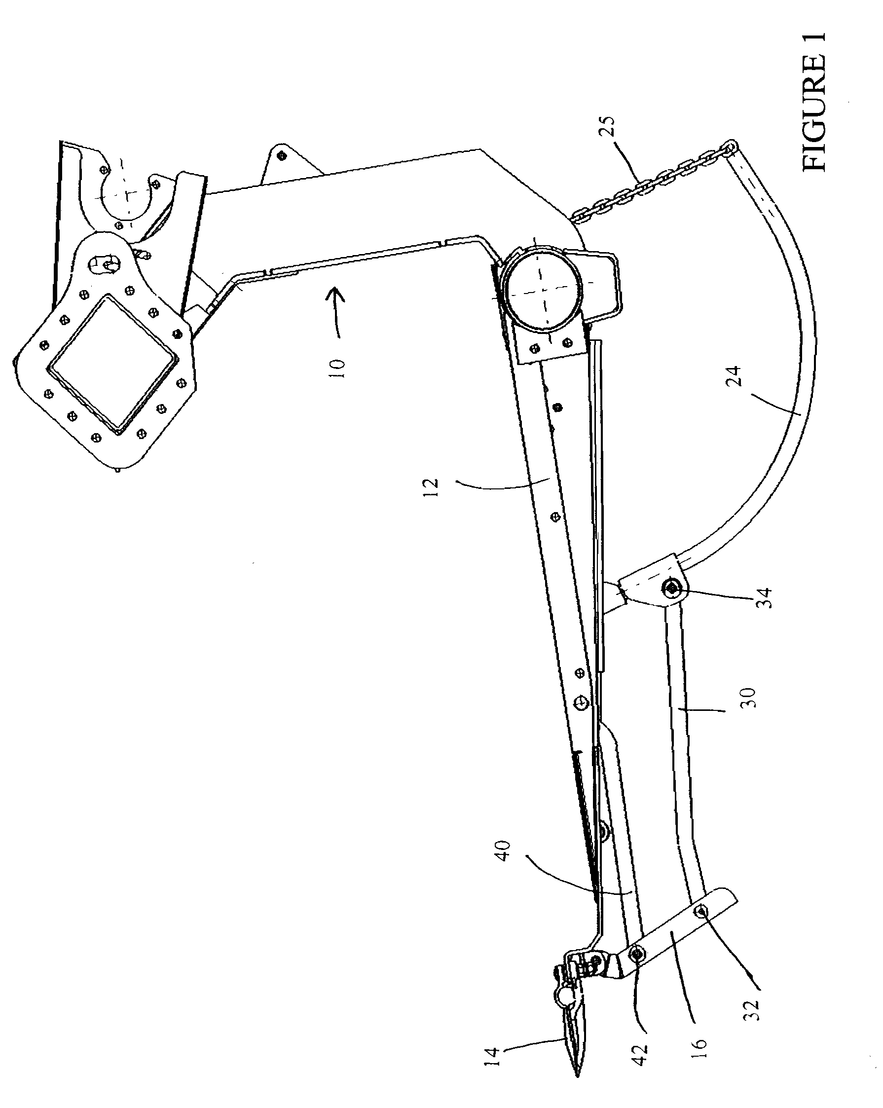
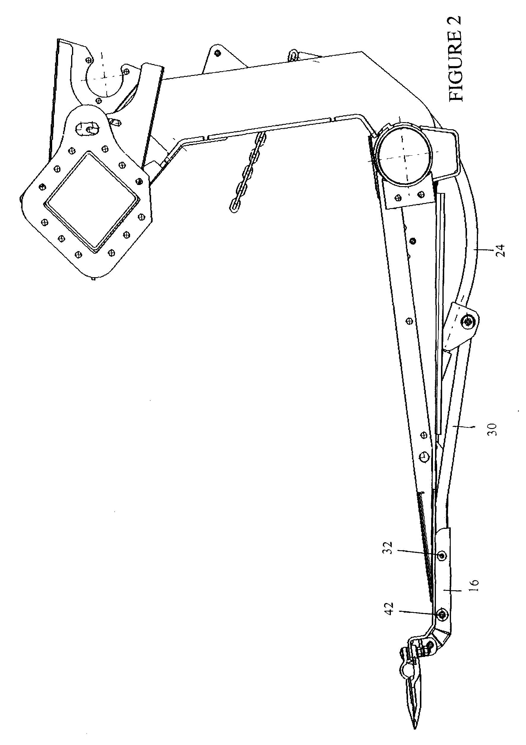
[0023]Referring now to the drawings wherein like reference numbers indicated like elements, crop header 10 includes a bottom element 12 and, located foremost in the direction of travel, a cutter bar 14.

[0024]Pivotally mounted on or adjacent to said cutter bar 14 is a forward height sensor arm 16. In the depicted embodiment, forward height sensor arm 16 is relatively short and straight. Thus positioned, the forward ground sensor arm responds quickly to ground contour changes when the header is at a low cutting height.

[0025]As is best seen in FIGS. 3 and 4, just behind the cutter bar 14 is a forward horizontal frame plate 18. Just to the rear of that is a height sensor mounting bracket 20. Over the height sensor mounting bracket 20 and extending forward of it to a fixture on the forward plate 18 is a frame foot 22 (show...


PUM

PropertyMeasurementUnit
Heightaaaaaaaaaa

Abstract

The invention is a combination of a short ground sensor arm mounted close to the cutter bar and a longer rod mounted towards the rear of the header. The short front sensor and long rear sensor are connected by a linkage which translates motions from either sensor to the other sensor. A second linkage translates the motions of both sensors rearward to a protected area under the header which contains the potentiometer. This configuration transmits useful ground position signals to the header height controller in both low and high cutting heights. The invention advantageously reduces the likelihood of damage to the short front sensor when the machine is reversed since the longer rear sensor arm pulls the shorter forward sensor arm up by means of the linkage to a position where damage is unlikely.

Description

CROSS-REFERENCE TO RELATED APPLICATIONS[0001]NoneSTATEMENT REGARDING FEDERALLY SPONSORED RESEARCH[0002]Not Applicable.APPENDIX[0003]Not Applicable.BACKGROUND OF THE INVENTION[0004]1. Field of the Invention[0005]The present invention is in the field of crop harvesting equipment such as combines and harvesters.[0006]2. Related Art[0007]Agricultural machines such as combines and harvesters use headers to cut crop and move it into the machine for processing. The headers can be raised and lowered to cut the crop at various heights. Many headers are equipped with ground sensors that contact the ground as the header moves through a field during harvest. As the ground terrain changes the sensors move up and down in response. A potentiometer measures the angle of change of the ground sensors and continually sends an electric voltage to a computer controller which moves the header according to the signals from the ground sensors' constant contact with the ground contour. This keeps the header...

Claims


Application Information

Patent Timeline
IPC IPC(8): A01D75/28B23P11/00A01D41/14A01D34/28A01D47/00
CPCY10T29/49826A01D41/141
Inventor NATHAN, CRISTOPHPETERSEN, JENSTIPPERY, STEVE
Owner CLAAS SELBSTFAHRENDE ERNTEMASCHINEN GMBH
Why Eureka
Try Eureka