Fluid ejection device, driving method of fluid ejection device, and operating instrument

a technology of fluid ejection and driving method, which is applied in watering devices, horticulture, agriculture, etc., can solve the problems of substantially no tissue cutting capability and continuous nozzle at low speed

Inactive Publication Date: 2010-04-01
COLUMBIA PEAK VENTURES LLC
View PDF5 Cites 27 Cited by
  • Summary
  • Abstract
  • Description
  • Claims
  • Application Information

AI Technical Summary

Benefits of technology

[0020]By this method, ejection operation can be prohibited or ejecting force can be decreased when the fluid ejection opening does not contact the ejection target object or the object in the vicinity of the ejection target object. Thus, ejection of fluid in an unexpected direction and scattering of substances cut thereby can be prevented when the fluid ejection opening is separated from the ejection target object or the object in the vicinity of the ejection target object by operation error or the like of a user (hereinafter referred to as operator as well).
[0051]According to this structure, larger vibrating force is generated. Thus, an object to be vibrated can be greatly vibrated, and the detection accuracy of the level of vibration can be increased.Thirteenth Aspect

Problems solved by technology

In this condition, delivery of fluid from the nozzle is continuous at low speed, producing substantially no tissue cutting capability.

Method used


Image

  • Fluid ejection device, driving method of fluid ejection device, and operating instrument
  • Fluid ejection device, driving method of fluid ejection device, and operating instrument
  • Fluid ejection device, driving method of fluid ejection device, and operating instrument

Examples


first embodiment

[0079]A first embodiment according to an aspect of the invention is hereinafter described with reference to the drawings. FIGS. 1 through 9 show a fluid ejection device, a driving method of the fluid ejection device, and an operating instrument according to the first embodiment.

[0080]The fluid ejection device according to an aspect of the invention can be used for various applications such as drawing by ink or the like, cleaning of minute object and structure, cutting and removal of objects, and operation scalpels. In this embodiment, a water pulse scalpel (fluid ejection device and operating instrument) appropriately used for opening or removing tissue of a living body by cutting will be described as an example. Thus, fluid used in this embodiment is water, physiological salt water, liquid medicine or the like.

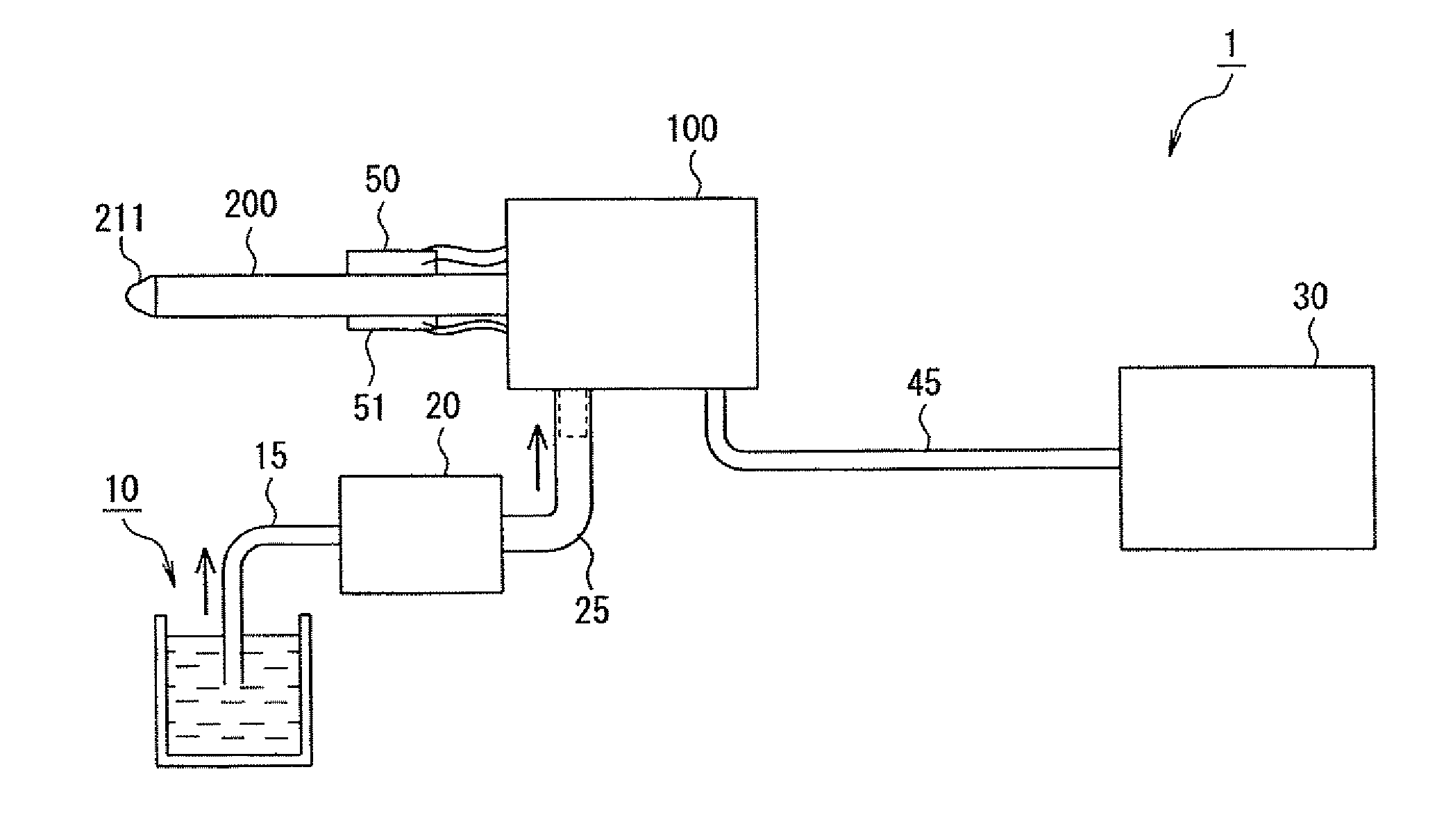
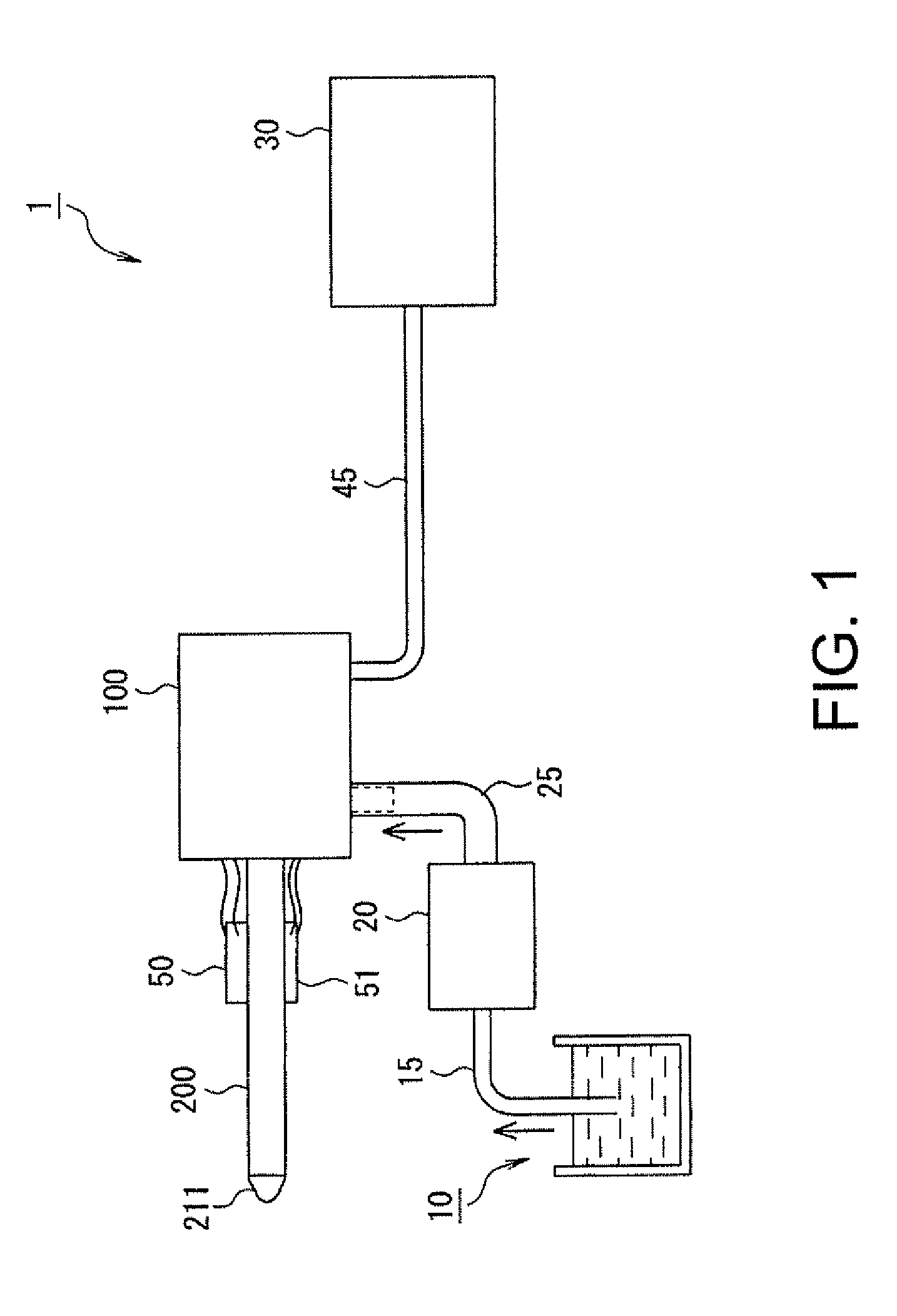
[0081]Initially, the structure of the fluid ejection device according to this embodiment is explained with reference to FIG. 1. FIG. 1 illustrates a general structure of a fl...

second embodiment

[0238]A second embodiment according to an aspect of the invention is hereinafter described. FIGS. 12 through 14 show a fluid ejection device, a driving method of a fluid ejection device, and an operating instrument according to the second embodiment of an aspect of the invention.

[0239]The second embodiment is different from the first embodiment in that components such as a suction pipe and a pump disposed in such positions as to cover the connection flow path pipe 200 are equipped to suck an object close to the nozzle 211 and give sucking force, respectively, and that the vibration generating piezoelectric element 50 and the distortion gauge 51 are provided on the outer circumferential surface of the suction pipe. Other parts are similar to those of the first embodiment. In the following description, only the different parts are discussed in detail. Similar reference numerals are given to similar parts, and explanation of the similar parts is not repeated.

[0240]The structure of the ...

third embodiment

[0273]A third embodiment according to an aspect of the invention is hereinafter described. FIGS. 15A through 17B show a fluid ejection device, a driving method of a fluid ejection device, and an operating instrument according to the third embodiment of an aspect of the invention.

[0274]The third embodiment is different from the first and second embodiments in that application of vibrating force to the connection flow path pipe 200 or the suction pipe 700 and detection of the level of vibration are achieved by time divisions using a single piezoelectric element provided on the connection flow path pipe 200 or the suction pipe 700. Thus, a part of the drive unit 30 is different from the drive unit 30 of the first and second embodiments. Other parts are similar to those of the first and second embodiments. In the following description, only the different parts are discussed in detail. Similar reference numerals are given to similar parts, and explanation of the similar parts is not repe...


PUM


Abstract

A fluid ejection device includes: a fluid chamber whose capacity is variable; an inlet flow path and an outlet flow path communicating with the fluid chamber; a capacity changing unit which changes the capacity of the fluid chamber; a fluid supplying unit which supplies fluid to the inlet flow path; a fluid ejection opening disposed at an end of the outlet flow path opposite to an end communicating with the fluid chamber; a vibrating unit which vibrates a component in the vicinity of the fluid ejection opening; a vibration detecting unit which detects the level of vibration of the component in the vicinity of the fluid ejection opening; and an operation control unit which controls operation of the capacity changing unit based on the level of the vibration detected by the vibration detecting unit.

Description

[0001]Japanese Patent Application No. 2008-256092 filed on Oct. 1, 2008, is hereby incorporated by reference in its entirety.BACKGROUND[0002]1. Technical Field[0003]The present invention relates to a fluid ejection device which ejects fluid at high speed, and more particularly to a fluid ejection device, a driving method of a fluid ejection device, and an operating instrument capable of controlling fluid ejection according to contact condition between an ejection target object and an ejection end.[0004]2. Related Art[0005]A fluid ejection device which opens or removes tissue of a living body by cutting has been proposed by the present inventors (see JP-A-2008-82202).[0006]This fluid ejection device includes: a pulse generating unit which has a fluid chamber whose capacity is variable, inlet flow path and outlet flow path communicating with the fluid chamber, a capacity changing unit for changing the capacity of the fluid chamber according to supply of driving signals; a connection f...

Claims


Application Information

Patent Timeline
Patent Type & Authority Applications(United States)
IPC IPC(8): A01G25/09
CPCA61B17/3203
Inventor SETO, TAKESHIKAWASUMI, KAZUOHAMA, YASUYOSHIKOJIMA, HIDEKIONO, YASUHIRO
Owner COLUMBIA PEAK VENTURES LLC
Why Eureka
Try Eureka