
Airbag

a technology of airbags and airbags, applied in the field of airbags, can solve the problems of airbags being unrecyclable due to the difference between materials of the coating and the fabric, and achieve the effect of preventing the formation of a hole due to inflation gas and scorching

Active Publication Date: 2010-04-01
TOYODA GOSEI CO LTD
View PDF74 Cites 24 Cited by
  • Summary
  • Abstract
  • Description
  • Claims
  • Application Information

AI Technical Summary

Benefits of technology

The present invention provides an airbag that is lightweight, cost-saving, easy to manufacture and recyclable. The airbag includes a body cloth made of polyamide woven fabric, a supplementary cloth made of polyamide woven fabric, and a coating layer made of polyamide elastomer. The supplementary cloth is bonded to the body cloth using a heat sealing process with the coating layer, and the coating layer acts as a protective membrane to prevent gas leakage. The airbag is easy to manufacture, recyclable, and can be used as a recycled material of polyamide easily. The invention also provides a simplified manufacturing process and improved handleability of the airbag.

Problems solved by technology

Further, if the coating is composed of rubber or polyurethane whereas the fabric forming the base cloths is formed of polyamide fiber, the difference of materials of the coating and fabric would make the airbag unrecyclable.

Method used


Image

  • Airbag
  • Airbag
  • Airbag

Examples


first embodiment

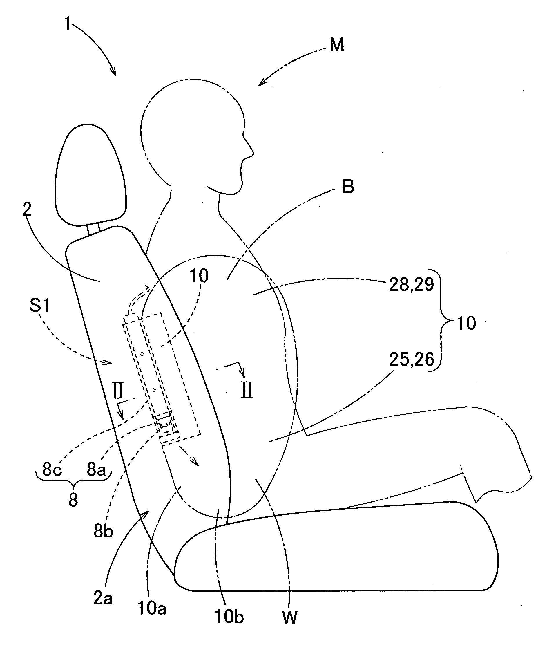
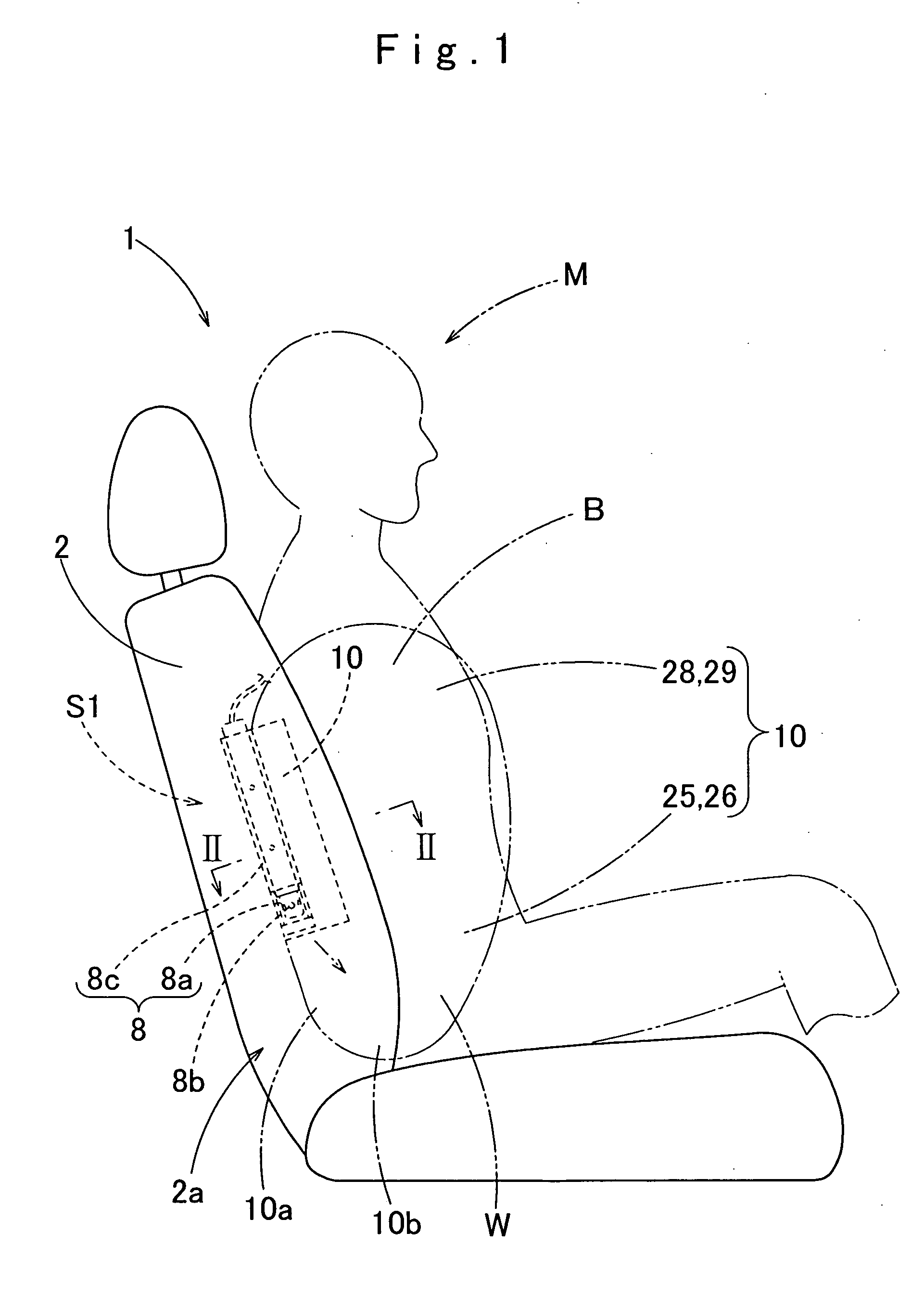
[0070]As shown in FIG. 1, an airbag 10 according to the invention is described for illustrative purpose as is used in an airbag apparatus S1 mounted on an outer lateral 2a of a seat back 2 of a seat 1 of a vehicle.

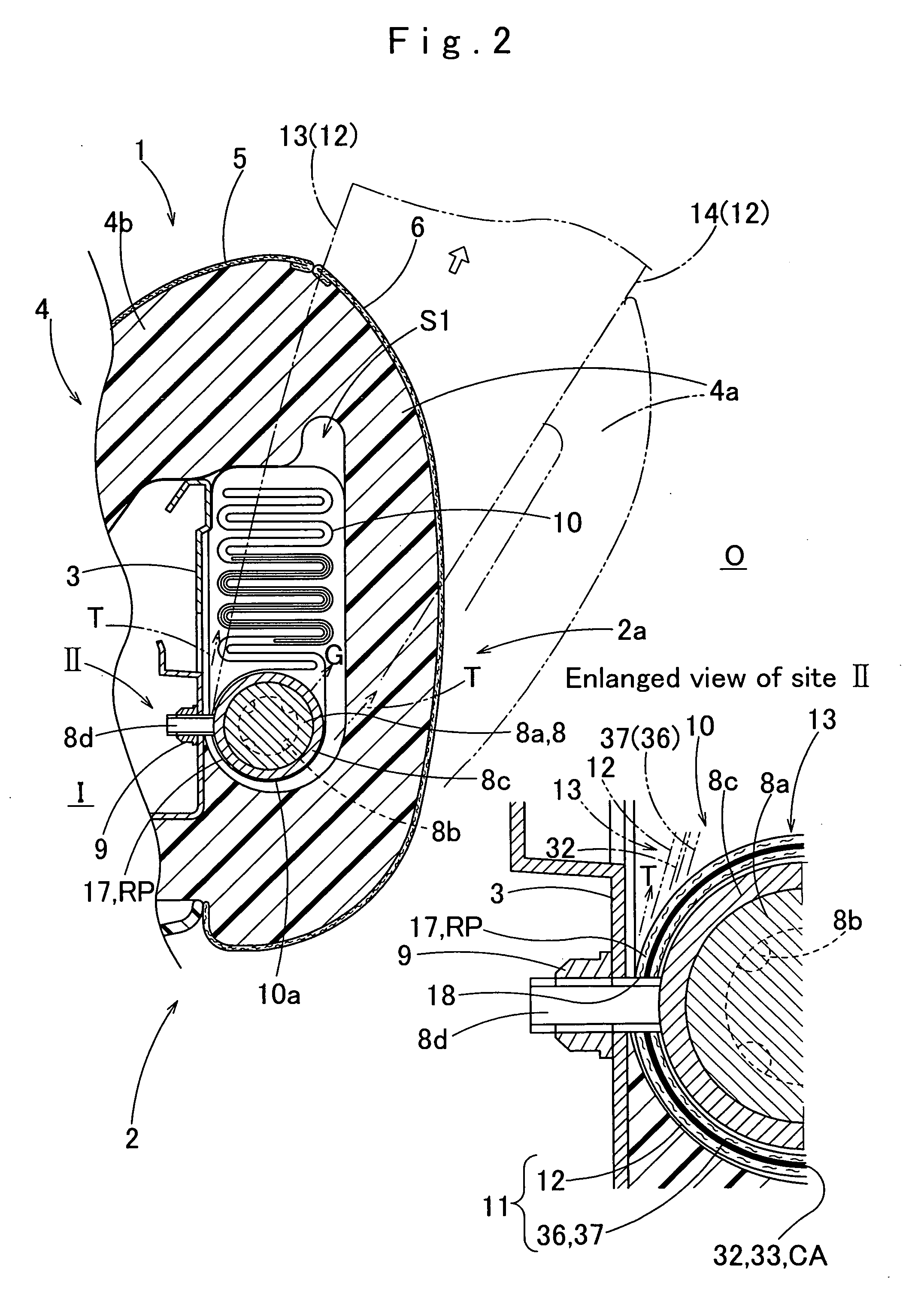
[0071]The seat back 2 includes a frame 3 extending generally vertically. As shown in FIG. 2, the airbag apparatus S1 is secured to the frame 3 by fastening bolts 8d of a later-described inflator 8 with nuts 9. In FIG. 2, a member indicated at 4 is a cushion, and members indicated at 5 and 6 are surface skins made of decoration fabric or the like. The right edge portion 4a of the cushion 4 covers the airbag apparatus S1 on the front and the outer side. Upon deployment of the airbag 10, the edge portion 4a is pushed by the airbag 10 and separated from a center part 4b of the cushion 4.

[0072]The airbag apparatus S1 includes an airbag 10 and an inflator 8 housed inside the airbag 10 for supplying the airbag 10 with inflation gas.

[0073]The inflator 8 includes a body 8a which is...

second embodiment

[0122]Manufacturing of the airbag 60 of the second embodiment is now described. Firstly, the first base cloth 75, second base cloth 76 of the body cloth 62, the reinforcing cloth 87 and cloth members 89 and 90 of the redirecting cloth 88 are cut out from the fabric 39. Then the coating composition CM is applied to the bond area 83 and extended area 84 of the first base cloth 75, the reinforcing cloth 87 and the locations of the mounting area 69 on the cloth members 89 and 90 to provide the coating layer 82 as shown in FIGS. 13 to 16. Thus provided are a component cloth 91 (body cloth 62), a component cloth 92 (cloth member 89), a component cloth 93 (cloth member 90) and a component cloth 94 (reinforcing cloth 87). Then these component cloths 91, 92, 93 and 94 are bonded together. Specifically, the body cloth 62 (component cloth 91) is laid on a support bed of a heat press machine with the coating layer 82 located on the top surface (which is to be the inner surface) 62a, and the clo...


PUM


Abstract

An airbag includes a body cloth made of polyamide woven fabric and constituting a circumferential wall of the airbag. The body cloth includes on the inner surface a bond area having a coating layer of polyamide elastomer and to which a supplementary cloth made of polyamide woven fabric is bonded, an extended area having a same coating layer of polyamide elastomer as on the bond area, and an uncoated area that has no coating layer. The coating layer on the bond area is used as heat sealable adhesive that adheres the supplementary cloth to the body cloth whereas that on the extend area is arranged in such a manner as to be exposed to inflation gas upon airbag inflation so as to act as a protective membrane for preventing gas leakage.

Description

[0001]The present application claims priority from Japanese Patent Application No. 2008-252769 of Naruse et al., filed on Sep. 30, 2008 and Japanese Patent Application No. 2009-150258 of Naruse et al., filed on Jun. 24, 2009, the disclosures of which are hereby incorporated into the present application by reference.BACKGROUND OF THE INVENTION[0002]1. Field of the Invention[0003]The present invention relates to an airbag inflatable with inflation gas.[0004]2. Description of Related Art[0005]JP8-104194 A discloses an airbag that includes a body cloth constituting a circumferential wall, a supplementary cloth applied to the inner surface of the body cloth for reinforcement or the like and an adhesive arranged between the body cloth and supplementary cloth for adhering the supplementary cloth to the body cloth. The airbag is manufactured only by adhesion and without sewing work.[0006]JP6-227346 A discloses an airbag that includes a body cloth, a supplementary cloth and an adhesive used ...

Claims


Application Information

Patent Timeline
Patent Type & Authority Applications(United States)
IPC IPC(8): B60R21/16B60R21/20B60R21/205B60R21/207B60R21/231B60R21/2346B60R21/235
CPCB60R21/207B60R2021/23533B60R2021/23514B60R21/235
Inventor NARUSE, MOTOAKIKOBAYASHI, HIROYUKIKAJIRO, MASAMICHI
Owner TOYODA GOSEI CO LTD
Learn More