Antenna conductor layout method and antenna array fabricated thereby
- Summary
- Abstract
- Description
- Claims
- Application Information
AI Technical Summary
Benefits of technology
Problems solved by technology
Method used
Image
Examples
first embodiment
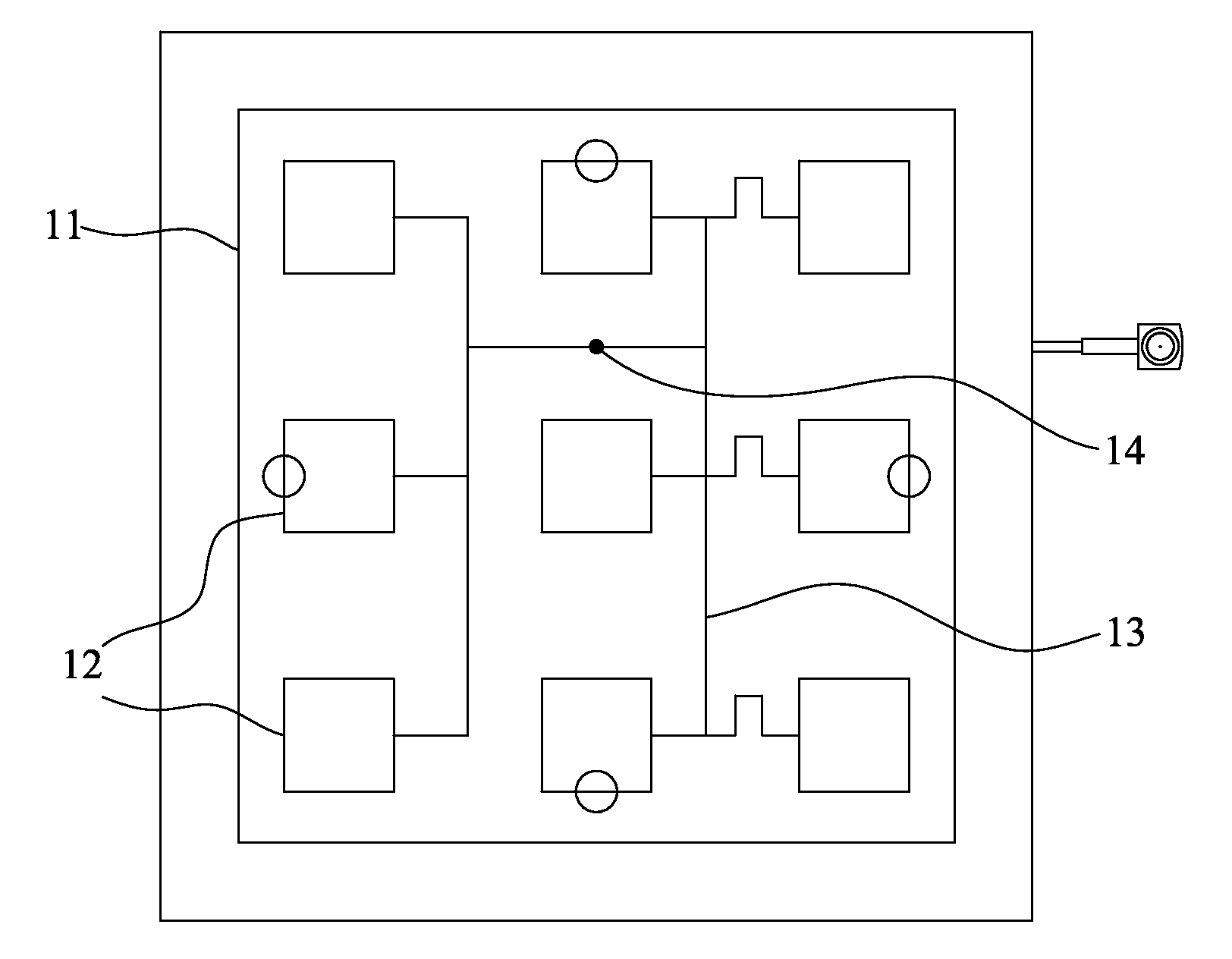
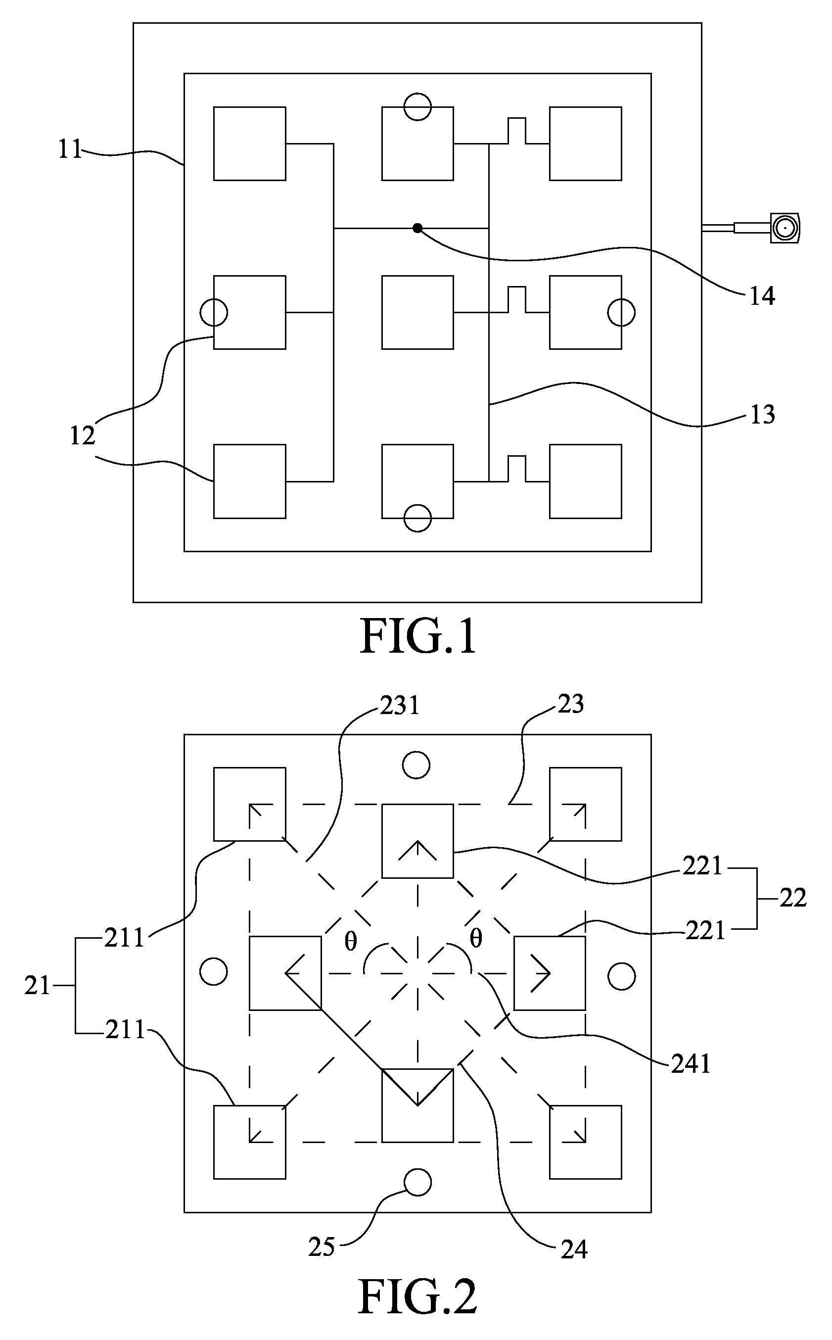
[0019]Referring to FIG. 2, a top view of an antenna array according to the present invention is shown. The antenna array of the present invention comprises the first conductor array 21 and the second conductor array 22. In the first conductor array 21, a plurality of first conductors 211 are arranged to form a rectangular layout, and the centers of all the first conductors 211 are connected to form a first rectangle 23. In the embodiment of FIG. 2, four pieces of first conductors 211 are used to form the first conductor array 21. The diagonals of the first rectangle 23 are defined to be first axes 231. In the second conductor array 22, a plurality of second conductors 221 is also arranged to form a rectangular layout, and the centers of all the second conductors 221 are connected to form a second rectangle 24. In the embodiment shown in FIG. 2, four pieces of second conductors 221 are used to form the second conductor array 22. The diagonals of the second rectangle 24 are defined to...
second embodiment
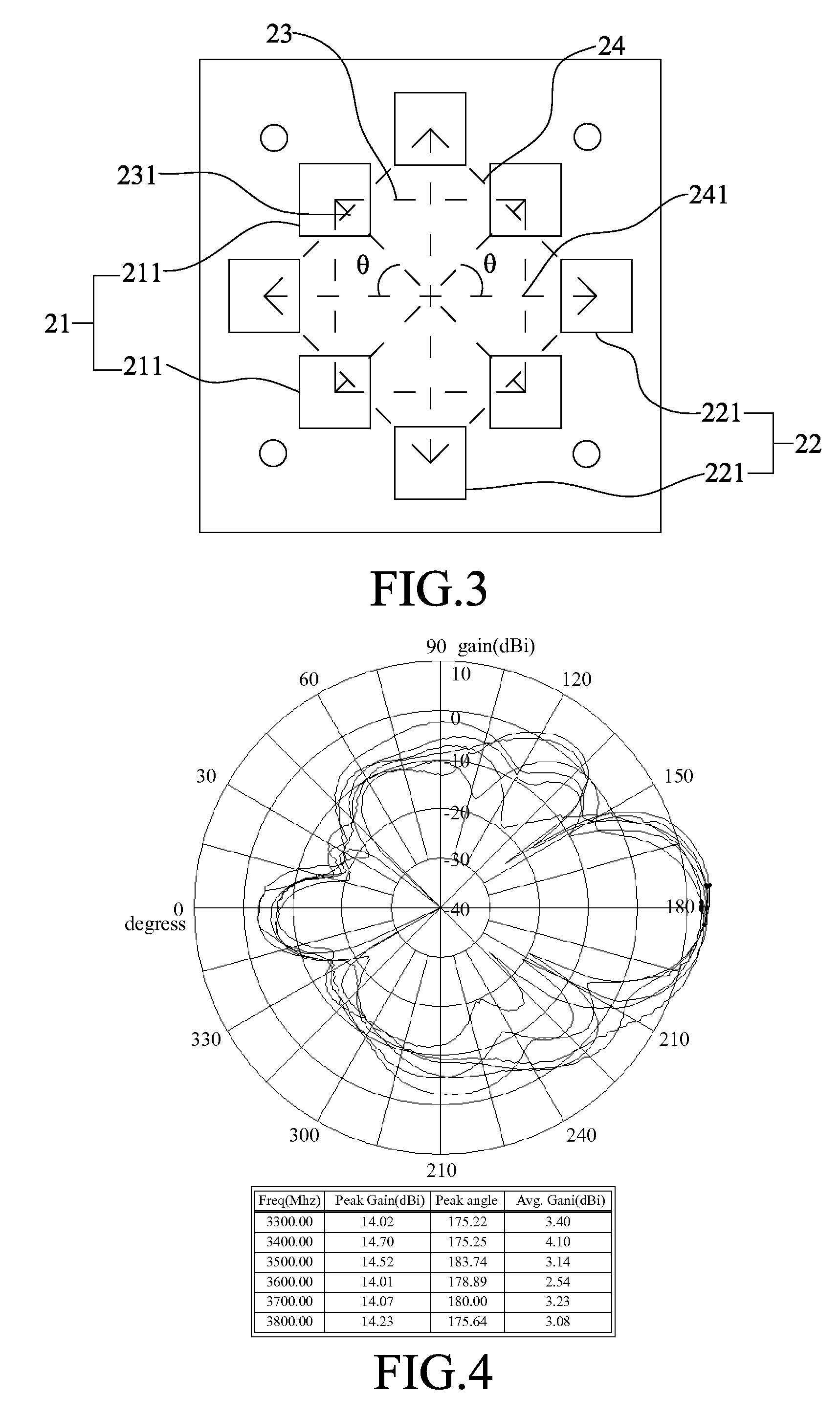
[0023]Referring to FIG. 3, a top view of an antenna array according to the present invention is shown. In this embodiment, the first conductors 211 of the first conductor array 21 are moved inward from the perimeter, and the second conductors 221 of the second conductor array 22 are moved outward from the interior. In this embodiment, the first conductors 211 are arranged to form a rectangular layout, and the second conductors 221 are also arranged to form a rectangular layout. The diagonals of the first and second conductor arrays 21 and 22 are also defined to be the first and second axes 231 and 241.
[0024]No matter where the installation holes 25 and the screws are arranged, the conductors can always be appropriately disposed according to the principle demonstrated by the embodiments described above, whereby designing the mechanism and controlling the radiation pattern becomes easier.
[0025]Referring to FIG. 4, a diagram shows the measurement results of the radiation pattern of the...
third embodiment
[0026]Referring to FIG. 5, a partially-enlarged view schematically shows that an antenna array is integrated with a wireless communication device according to the present invention. In this embodiment, an antenna array 50 is installed in a wireless communication device 5, and the first conductor array 51 and the second conductor array 52 are arranged on a substrate 53. A plurality of metal cables are arranged symmetrically to form a feeder network 54, and feeder network 54 connects the first conductor array 51 and the second conductor array 52. The feeder network 54 has a feeder point 54a arranged near the intersection of the first axes of the first conductor array 51 and the second axes of the second conductor array 52. A plurality of support elements 55 is distributed on the substrate 53 and used to support the substrate 53. A ground plane 56 carries the support elements 55. Additionally, a feeder cable 57 has a central wire connected to the feeder point 54a and an external wire c...
PUM
| Property | Measurement | Unit |
|---|---|---|
| Time | aaaaa | aaaaa |
| Angle | aaaaa | aaaaa |
| Angle | aaaaa | aaaaa |
Abstract
Description
Claims
Application Information
 - R&D
- Intellectual Property
- Life Sciences
- Materials
- Tech Scout
- Unparalleled Data Quality
- Higher Quality Content
- 60% Fewer Hallucinations
Browse by: Latest US Patents, China's latest patents, Technical Efficacy Thesaurus, Application Domain, Technology Topic, Popular Technical Reports.
© 2025 PatSnap. All rights reserved.Legal|Privacy policy|Modern Slavery Act Transparency Statement|Sitemap|About US| Contact US: help@patsnap.com


