Dot position measurement method, dot position measurement apparatus, and computer readable medium

a technology of position measurement and dot position, which is applied in the direction of printing, other printing apparatus, etc., can solve the problems of large size of read image data, inability to complete reading in a single pass, and affecting the accuracy of image recording, so as to reduce the processing time and reduce the data processing time , the effect of preventing the increase of the computer performance required for this processing

Inactive Publication Date: 2010-04-01
FUJIFILM CORP
View PDF4 Cites 11 Cited by
  • Summary
  • Abstract
  • Description
  • Claims
  • Application Information

AI Technical Summary

Benefits of technology

[0165]In this embodiment, the direction of the dot impact positions on the test pattern to be measured is the same as the main scanning direction of the scanner (FIG. 10), and hence reading is performed by lowering the scanner reading resolution in the sub-scanning direction with respect to that of the main scanning direction (FIG. 11). This allows even commercially available scanners to read a whole A3 page in one pass and allows the measurement time to be shortened.
[0166]Furthermore, the amount of read image data is approximately 257 MB (at 2400 DPI for main scanning and 200 DPI for sub-scanning) and therefore small. This leads to a valuable reduction in the data processing time and prevents the computer performance required for this processing from increasing. Hence, the highly accurate dot position measurement which is aimed at can be implemented at relatively low cost.
[0167]Moreover, in this embodiment, an average profile image, obtained by performing a partial averaging in terms of the line longitudinal direction (sub-scanning direction of the scanner) when determining a line position in a read image, is formed, and this average profile image is subjected to a filter process. Scattering of ink (satellite droplets) and the contrast of dirt are relatively lowered due to the aforementioned reading at a low resolution in the sub-scanning direction, the averaging, and the filtering process. As a result, there is no requirement for a special method of removing dirt.
[0168]Furthermore, the averaging processing simultaneously reduces the adverse effect of irregular noise in the averaging direction, which has the effect of increasing the reliability of tone values and improving the accuracy of the algorithm for determining the position based on these tone values. The filtering process also reduces irregular noise components and sampling distortion, thereby smoothing the profile image and improving reliability in terms of the line position.
[0169]Furthermore, as a result of the processing (W / B correction processing) to correct tone values, in an averaged profile image, on the basis of the white background close to each line and the ink density, distortion of the profile image, caused by the effects of scanner flare or disruption of the recording paper, is corrected, together with reducing the shading of the scanner in the main scanning direction. Positional accuracy based on tone values can be improved by correcting the tone values in this way.
[0170]Moreover, with this embodiment, a line position is calculated by using a plurality of average profile images with regions (ROI) for calculating the average profile displaced from one another by a fixed amount in a line longitudinal direction, and the plurality of line positions obtained are averaged. This processing adjusts the relative positional relationship (so-called sampling phase) between the read lines and scanner reading elements, thereby improving the line position accuracy still further.

Problems solved by technology

However, with line-head image forming apparatuses, there is the problem that streaks or unevenness of the image recorded on the recording medium occurs due to inconsistencies during production such as displacement of the ejection unit.
Although higher resolutions are desirable for reading devices (scanners) in order to improve impact position accuracy, higher reading device resolutions cause (1) problems with the size of read image data, and (2) the problem that reading is not completed in a single pass.
Such a large volume of data is time-consuming even when the data is read to a hard disk device (HDD).
Moreover, since current commercial scanners have a limited reading range at the highest resolution (4800 DPI for an A4 scanner and 2400 DPI for an A3 scanner, for example), reading cannot be performed all at once at the maximum reading range.
Even if processing is performed to reduce the image data and the write time is reduced, dividing up an image causes problems, namely a larger image data capacity, and an increase in the reading time.
The technologies disclosed in Japanese Patent Application Publication Nos. 2008-44273 and 2008-80630 are faced by the problem that, because the main and sub-scanning resolutions during reading are the same, when these technologies are used, an image cannot be read all at once, or the processing time is long due to the large size of the image to be processed.

Method used


Image

  • Dot position measurement method, dot position measurement apparatus, and computer readable medium
  • Dot position measurement method, dot position measurement apparatus, and computer readable medium
  • Dot position measurement method, dot position measurement apparatus, and computer readable medium

Examples


modified embodiment

[0181]A composition in which the functions of the dot position measurement apparatus 200 illustrated in FIG. 25 are incorporated in the inkjet recording apparatus is also possible. An embodiment in which a series of operations such as printing and then reading a measurement line pattern, and then performing dot position measurement by analyzing the image are carried out continuously by a control program of an inkjet recording apparatus, is also possible.

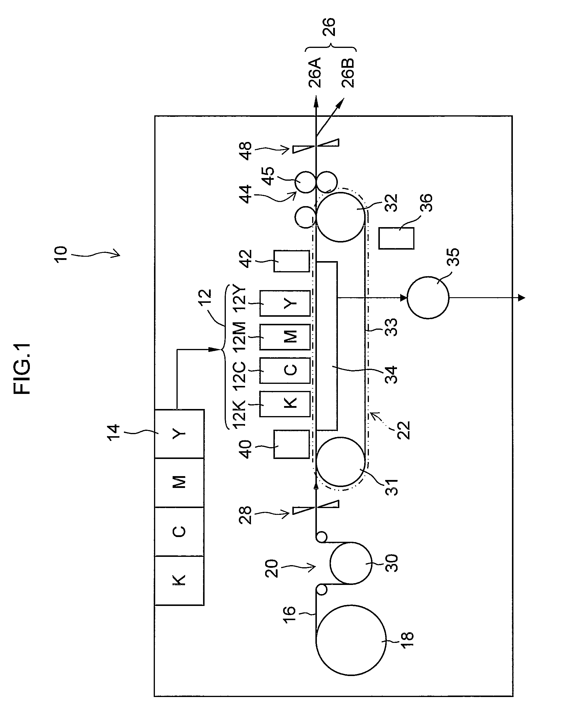
[0182]For example, a line sensor (print detection unit) for reading a print result may be provided downstream of the print unit 12 in the inkjet recording apparatus 10 illustrated in FIG. 1, and a measurement line pattern can be read with the line sensor.

[0183]In the respective embodiments described above, an inkjet recording apparatus using a page-wide full line type head having a nozzle row of a length corresponding to the entire width of the recording medium was described, but the scope of application of the present invention is n...


PUM


Abstract

A dot position measurement method includes: a line pattern formation step of recording dots continuously by a plurality of recording elements of a recording head while performing relative movement between the recording head and a recording medium in such a manner that a measurement line pattern including a plurality of lines of rows of the dots respectively corresponding to the plurality of recording elements is formed on the recording medium; a reading step of reading the measurement line pattern formed on the recording medium with an image reading apparatus in a state where a longitudinal direction of the plurality of lines of the measurement line pattern are directed to a sub-scanning direction of the image reading apparatus and a reading resolution in the sub-scanning direction of the image reading apparatus is lower than a reading resolution in a main scanning direction of the image reading apparatus in such a manner that an electronic image data indicating a read image of the measurement line pattern is acquired; a region allocating step of allocating a plurality of averaging regions where an image signal on the read image is averaged in terms of the sub-scanning direction, to different positions in terms of the sub-scanning direction of each of line blocks, each line block including the lines arranged in the main scanning direction; an average profile image forming step of averaging the image signal in terms of the sub-scanning direction in each of the plurality of averaging regions that have been allocated to the different positions and creating average profile images for positions in terms of the main scanning direction; an edge position determination step of determining positions of both edges of each of the lines according to the average profile images; an averaging region position determination step of determining positions of the lines in the plurality of averaging regions according to the positions of the both edges determined in the edge position determination step; and a line block position determination step of determining positions of the lines in the line blocks according to the positions of the lines in the plurality of averaging regions determined according to the average profile images corresponding to the plurality averaging regions respectively.

Description

BACKGROUND OF THE INVENTION[0001]1. Field of the Invention[0002]The present invention relates to a dot position measurement method, a dot position measurement apparatus, and a computer readable medium, and more particularly to dot position measurement technique suitable for measurement of a deposition position of a dot recorded by each nozzle of an inkjet head.[0003]2. Description of the Related Art[0004]One method of recording an image onto a recording medium such as recording paper is an inkjet drawing method in which an image is recorded by ejecting ink droplets in response to an image signal and causing the ink droplets to impact on the recording medium. As an image forming apparatus which employs such an inkjet drawing system, there exists a full-line head image drawing apparatus, in which an ejection unit (nozzle) which ejects ink droplets, is disposed in a line facing the whole of one side of the recording medium, and the recording medium is conveyed in a direction orthogonal...

Claims


Application Information

Patent Timeline
Patent Type & Authority Applications(United States)
IPC IPC(8): B41J29/38
CPCB41J29/393B41J2/2146
Inventor YAMAZAKI, YOSHIROU
Owner FUJIFILM CORP
Why Eureka
Try Eureka