

Droplet ejection apparatus and image forming apparatus
- Summary
- Abstract
- Description
- Claims
- Application Information
AI Technical Summary
Benefits of technology
Problems solved by technology
Method used
Image

Examples
Embodiment Construction
Configuration of Head Module
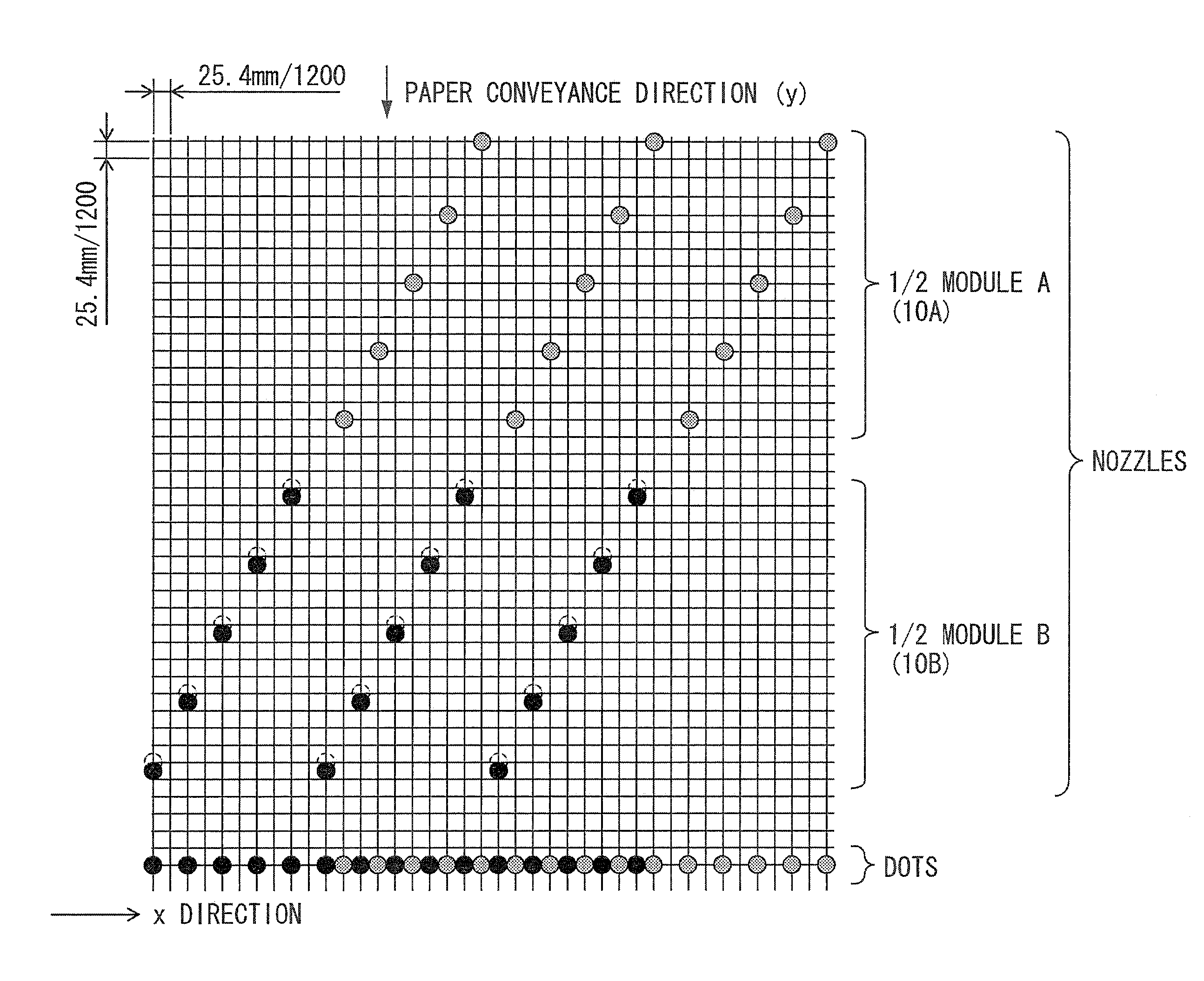
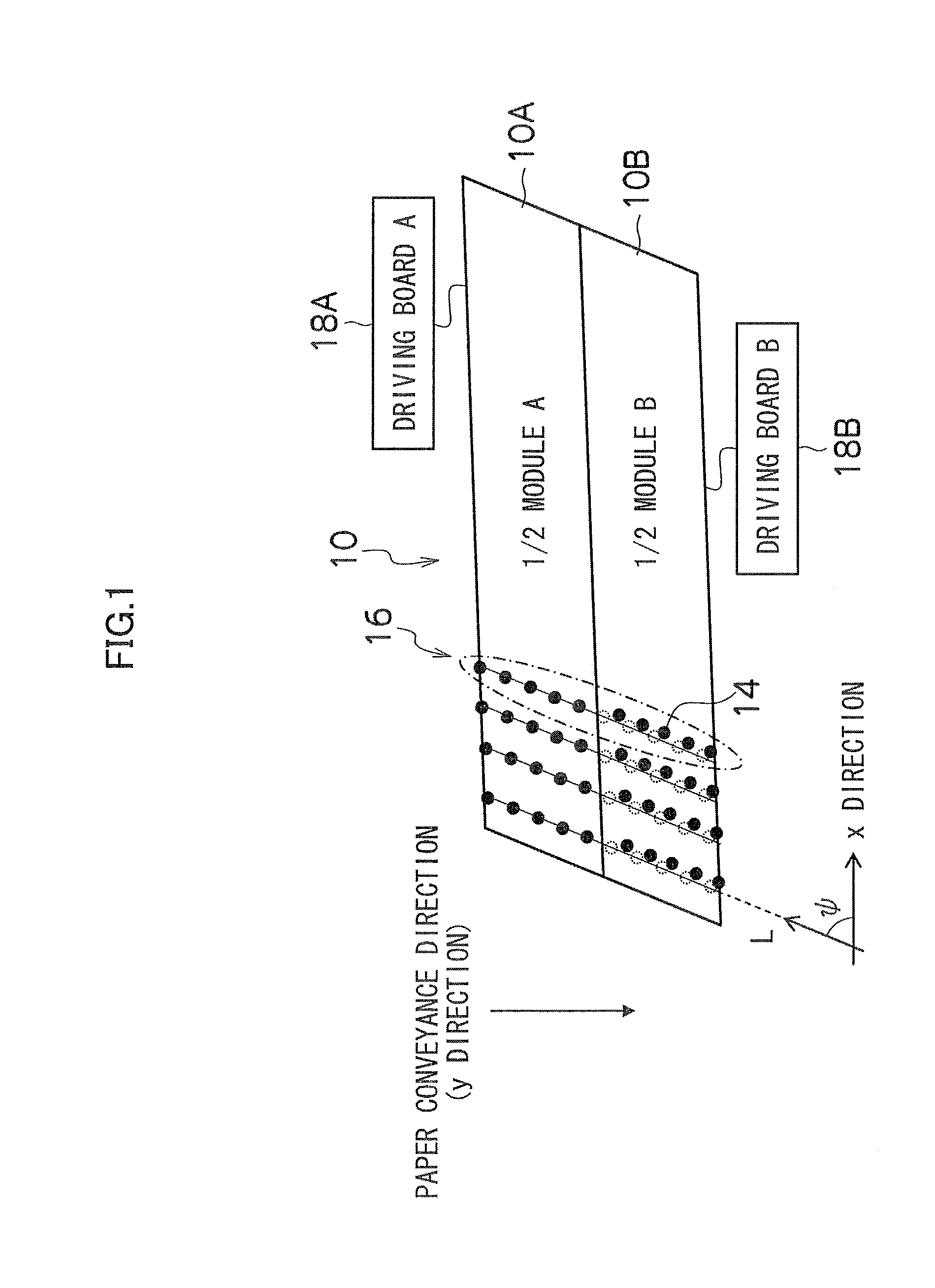
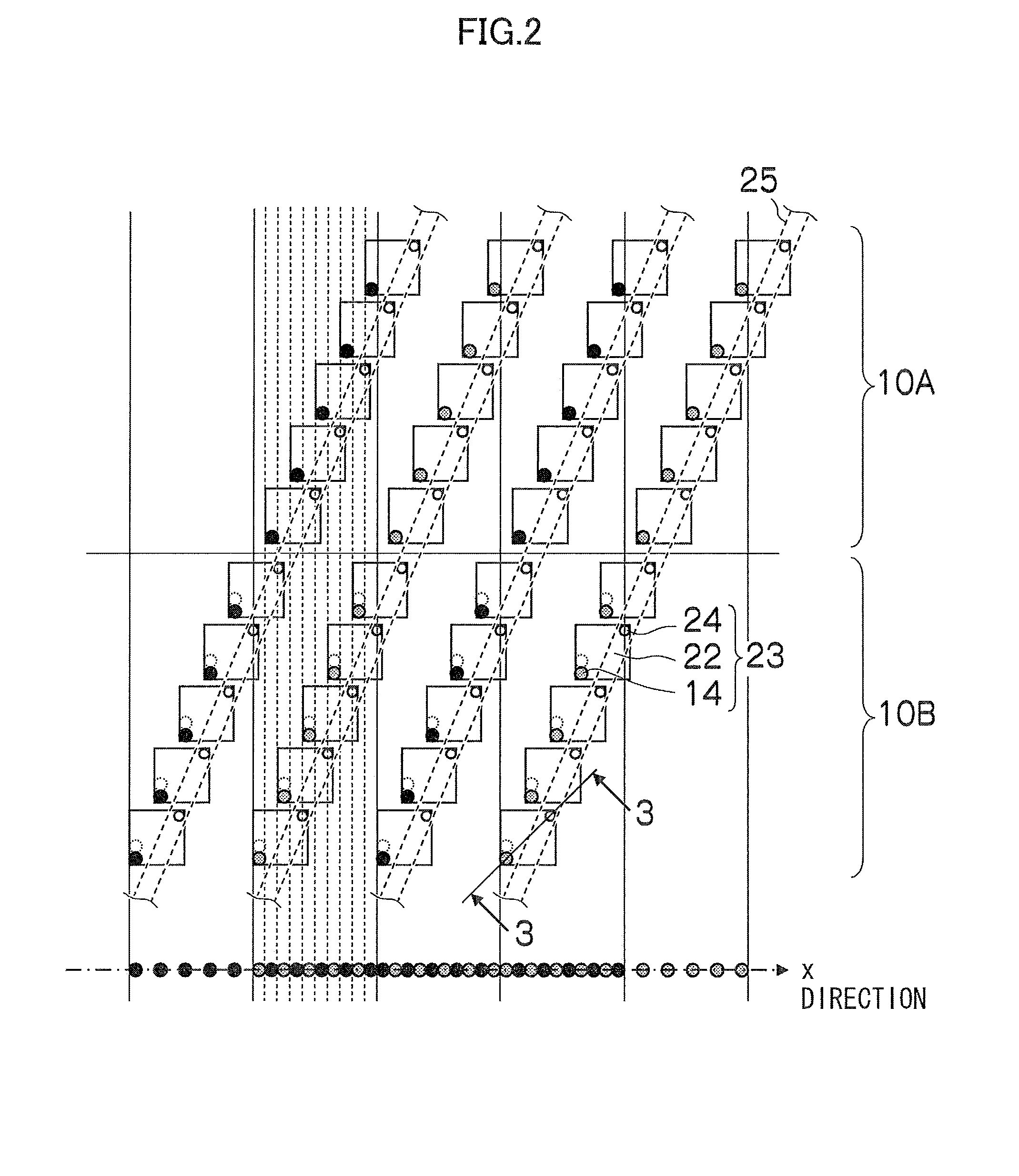
[0035]FIG. 1 is a schematic configuration diagram of a head module 10 constituting an inkjet head according to an embodiment of the present invention. FIG. 2 is an explanatory diagram for illustrating the relationship between an internal flow channel structure and droplet deposition points (dot positions) from nozzles within the head module.
[0036]In FIG. 1, a paper conveyance direction shown by a downward arrow is a y direction, and a paper widthwise direction (lateral direction) perpendicular to the y direction is an x direction. The head module 10 has a two-dimensional nozzle array in which a plurality of nozzle rows 16 each having a plurality of nozzles 14 are arranged along the x direction with a predetermined interval therebetween. The nozzles 14 are arranged in an inclined direction (L direction) intersecting with the x direction at an angle ψ. Focusing on one certain nozzle row (for example, one nozzle row surrounded by an alternate dash and dot li...
PUM
 Abstract
Description
Claims
Application Information