
Liquid crystal display device and its driving method

A liquid crystal display and display panel technology, applied to static indicators, instruments, etc., can solve problems such as affecting brightness, crosstalk effect, and image quality deterioration

Inactive Publication Date: 2004-09-29
SUNPLUS TECH CO LTD
View PDF0 Cites 6 Cited by
  • Summary
  • Abstract
  • Description
  • Claims
  • Application Information

AI Technical Summary

Problems solved by technology

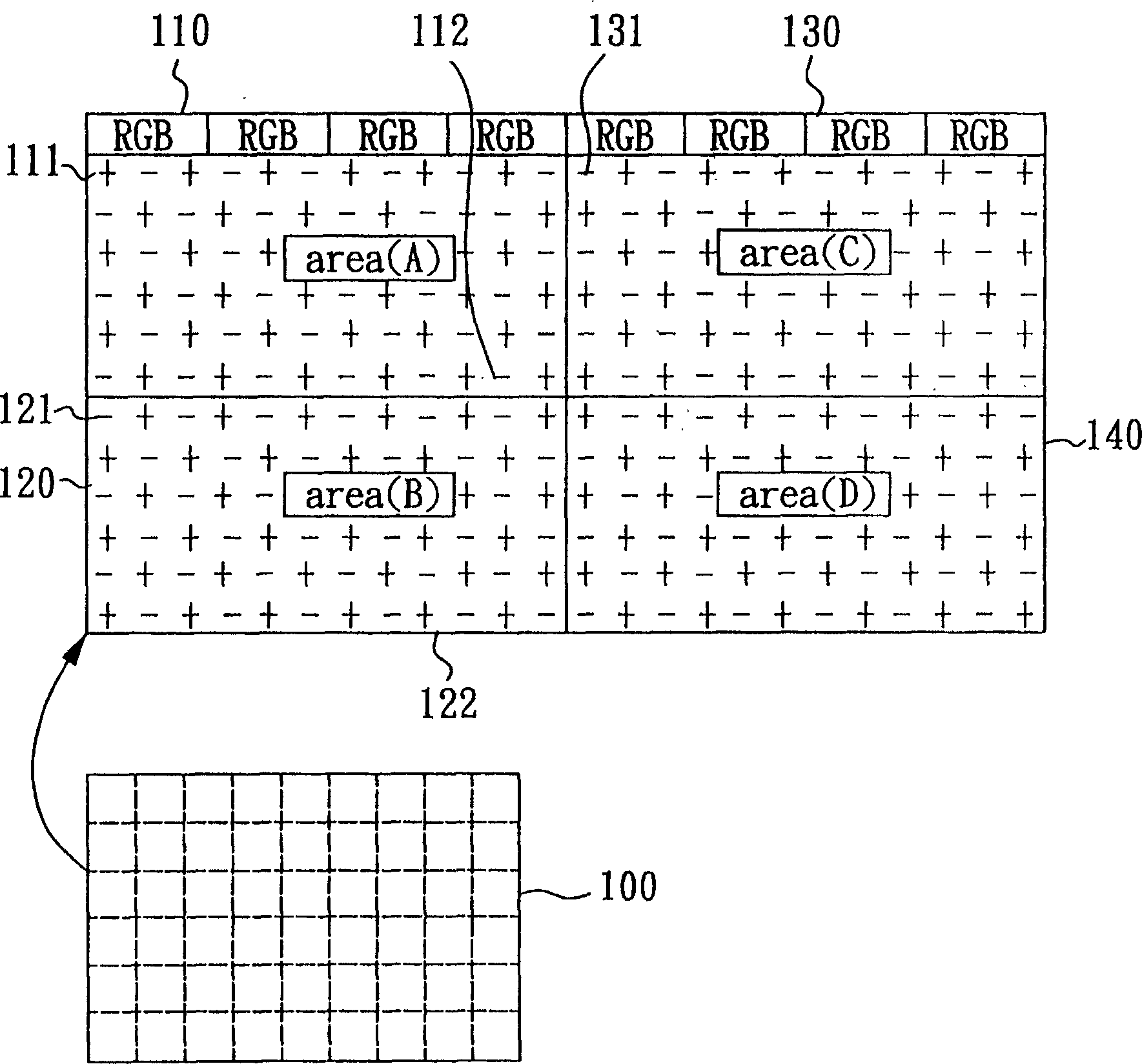
Since this approach is based on the picture blocks 110, 120, 130, 140, when the vertical (Column) signal of the display panel 100 is driven by time division multiplexing, if a certain picture (Pattern) makes a certain picture in the display panel 100 If the sum of effective voltages for driving liquid crystals of one polarity is much greater than that of the other polarity, crosstalk (Crosstalk) effect is prone to occur, that is, the image in a certain area of ​​the display panel 100 affects the brightness of adjacent areas, resulting in poor image quality.
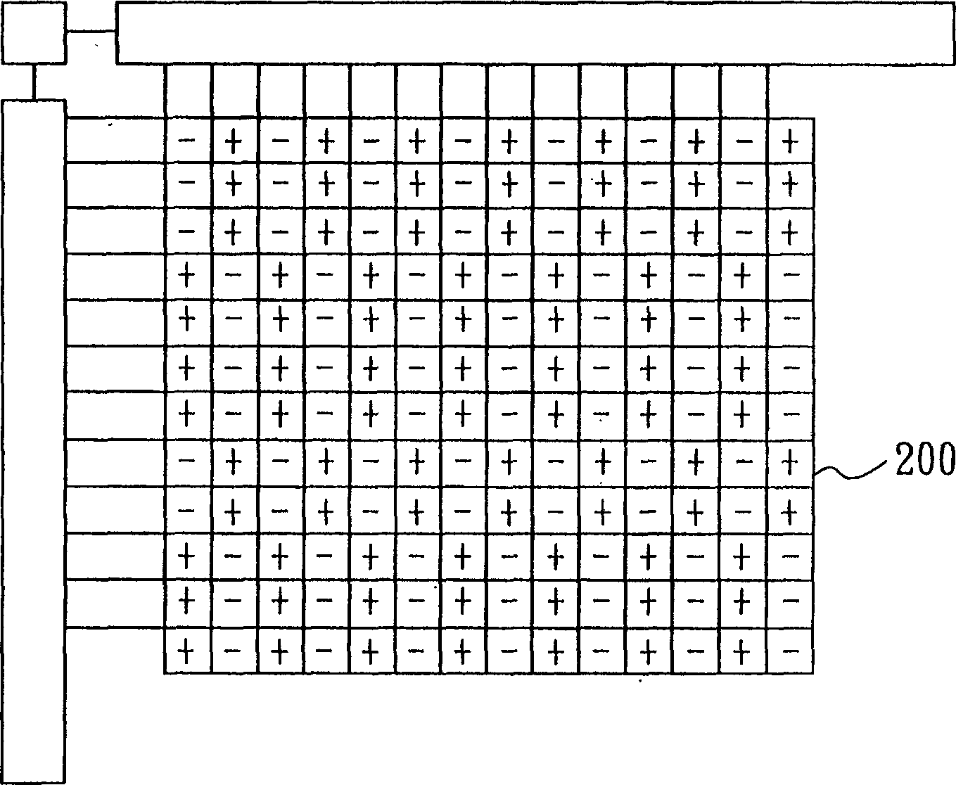
[0004] figure 2 It shows the practice of arranging the polarity of the panel 200 in the vertical direction (Data Line direction) to change irregularly, and the polarities of two adjacent picture blocks are opposite, because the horizontal direction (Row Line direction) is positive and negative Neighboring arrangement, so when the panel 200 longitudinal signal is time-division multiplexing drive, a specific picture will also appear. sound effect, making the image quality deteriorate

Method used


Image

  • Liquid crystal display device and its driving method
  • Liquid crystal display device and its driving method
  • Liquid crystal display device and its driving method

Examples


Embodiment Construction

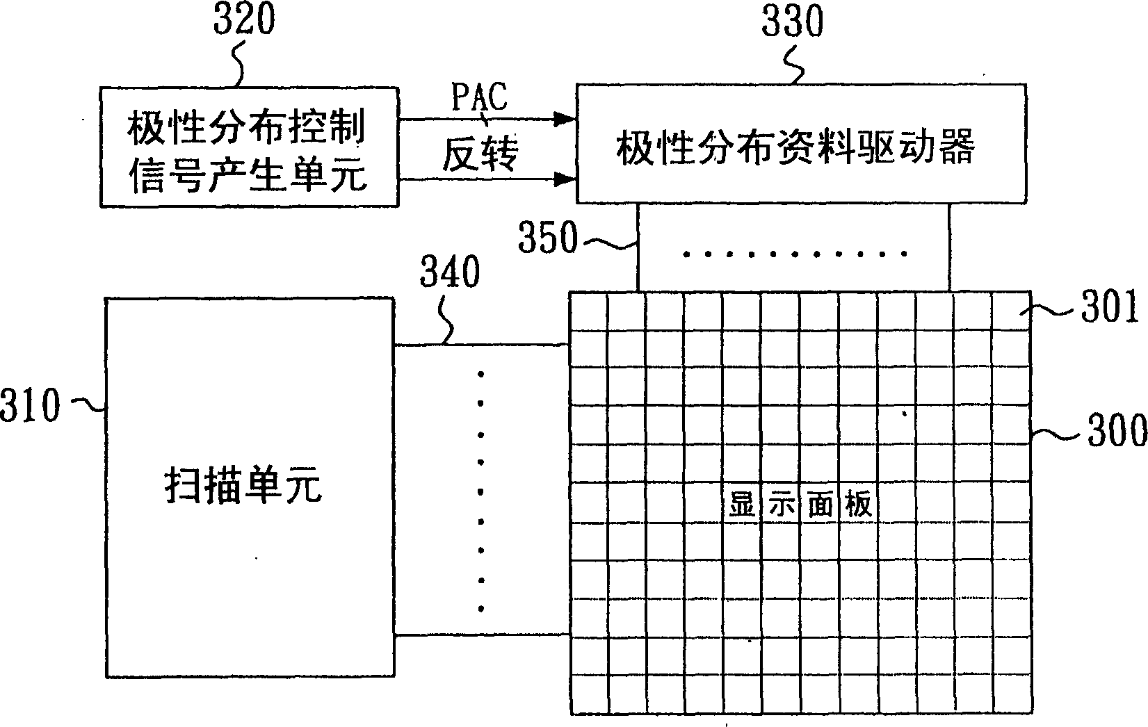
[0031] For preferred embodiments of the present invention, please refer to image 3 The structure diagram shown mainly includes the main components such as the display panel 300 , the scanning unit 310 , the polarity distribution control signal generation (PATG) unit 320 and the polarity distribution data driver (PPADD) 330 . Wherein, the display panel further includes a plurality of pixel units 301 . The scanning unit 310 is connected to the pixel unit 301 of the display panel 300 through a plurality of scanning lines 340, and the polarity distribution data driver 330 is connected to the pixel unit 301 of the display panel 300 through a data line 350 for controlling the pixels through the polarity distribution data driver 330 Polarity of unit 301. In this embodiment, the display panel 300 is preferably a liquid crystal display panel, the scanning unit 310 is preferably a gate drive integrated circuit (IC), and the polarity distribution control signal generation unit 320 is p...


PUM


Abstract

The present invention relates to one kind of LCD device and its driving method. A polar distribution controlling signal generating unit is used to generate polar distribution controlling signal output to the polar distribution data driver, and one aperiodic polar array is output to the display panel according to the polar distribution control signal to make pixel unit polarity in the panel in aperiodic distribution. Inside several frames, one half of the frames are complementary with the other half of the frame, that is to say, the polarity of all the pixel units in one half of the frames is opposite to that of all the pixel units in the other half of the frames.

Description

technical field [0001] The present invention relates to a flat display, in particular to a liquid crystal display device and a driving method thereof, which can be applied to a source driver integrated circuit (Source IC) or timing controller of a low temperature polysilicon (LTPS) thin film transistor liquid crystal display, and a thin film In the source drive integrated circuit or timing controller of transistor liquid crystal display and other drive circuits. Background technique [0002] With the development of the optoelectronic industry, flat panel displays have successfully replaced cathode ray tube (CRT) screens. The current flat panel display can be completed by a variety of different technologies, such as: liquid crystal display (LCD), thin film transistor liquid crystal display (TFT-LCD), or organic electroluminescence display (OLED), wherein, liquid crystal display and thin film transistor liquid crystal display The bias voltage is mainly used to control the ali...

Claims


Application Information

Patent Timeline
IPC IPC(8): G09G3/36
Inventor 饶永年周世宗林崑宗
Owner SUNPLUS TECH CO LTD
Learn More