Apparatus and method for biomedical imaging

a biomedical imaging and apparatus technology, applied in the field of imaging systems, can solve the problems of not allowing the viewer, patient and doctor cannot obtain the best perspective, and the cornea is difficult to examin

Inactive Publication Date: 2010-04-01
WARING IV GEORGE O
View PDF11 Cites 45 Cited by
  • Summary
  • Abstract
  • Description
  • Claims
  • Application Information

AI Technical Summary

Benefits of technology

[0007]An advantage of the present invention is to provide an imaging system, comprising: an imaging device for capturing two dimensional images; a computer operably connected to the imaging device controlling the imaging device; the computer having an image extraction software for controlling the capture of two dimensional images, the computer having a post production software for converting the two dimensional images into a three dimensional virtual environment image, creating multiple viewing points of the three dimensional virtual environment image, and for creating immersive omnidirectional viewing within the three dimensional virtual environment image; an input device connected to the computer for receiving commands; and an output device connected to the computer for displaying images.
[0008]Another advantage of the present invention is to provide an imaging method, comprising: optimizing an imaging device; capturing two dimensional images; converting the two dimensional images into a three dimensional virtual environment image; and creating a fly through sequence.
[0009]Additional features and advantages of the invention will be set forth in the description which follows, and in part will be apparent from the description, or may be learned by practice of the invention. The objectives and other advantages of the invention will be realized and attained by the structure particularly pointed out in the written description and claims hereof as well as the appended drawings. To achieve these and other advantages and in accordance with the purpose of the present invention, as embodied and broadly described, an imaging system, comprising: an imaging device for capturing two dimensional images; a computer operably connected to the imaging device controlling the imaging device; the computer having an image extraction software for controlling the capture of two dimensional images, the computer having a post production software for converting the two dimensional images into a three dimensional virtual environment image, creating multiple viewing points of the three dimensional virtual environment image, and for creating immersive omnidirectional viewing within the three dimensional virtual environment image; an input device connected to the computer for receiving commands; and an output device connected to the computer for displaying images.
[0010]In another aspect of the present invention, An imaging method, comprising: optimizing an imaging device; capturing two dimensional images; converting the two dimensional images into a three dimensional virtual environment image; and creating a fly through sequence.
[0011]It is to be understood that both the foregoing general description and the following detailed description are exemplary and explanatory and are intended to provide further explanation of the invention as claimed.

Problems solved by technology

Transparency, avascularity, and immunologic privilege make the cornea very difficult to examine.
However, due to limitations associated with the processing of large amounts of two dimensional images into three dimensional images, and the transparent nature of the cornea, conventional three dimensional images of the cornea and other areas of the patient's body do not allow the viewer to view the images from multiple viewing points, as well as multiple viewing points wherein the viewer has the capability to immerse their viewing perspective from within the cornea or body area of interest tissue itself at a cellular layer.
Without the ability to view the cornea or body area of interest from a multiple of viewing angles around the cornea or area of interest looking in and as well as from within the cornea or area of interest itself, the patient and doctor can not obtain the best perspective.
Currently Fourier domain Optical coherence tomography (OCT) like other imaging modalities are limited to omnidirectional volumetric three dimensional viewing of the cornea or selected body areas of interest.
Conventional three dimensional imaging of the cornea or body does not allow the viewer to pass through the cellular layers of the tissue with a single pass.

Method used


Image

  • Apparatus and method for biomedical imaging
  • Apparatus and method for biomedical imaging
  • Apparatus and method for biomedical imaging

Examples


Embodiment Construction

[0021]Reference will now be made in detail to an embodiment of the present invention, example of which is illustrated in the accompanying drawings.

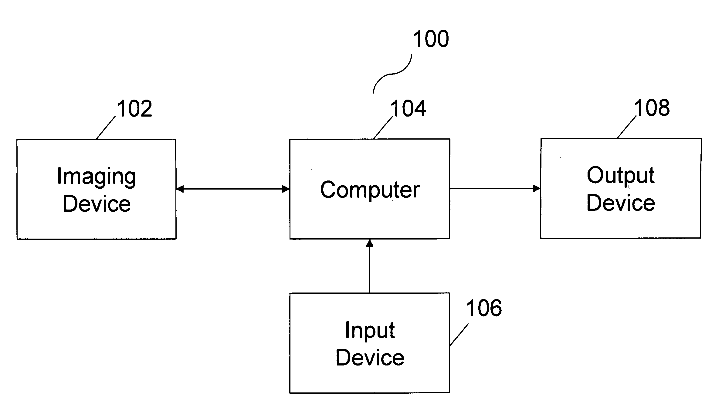
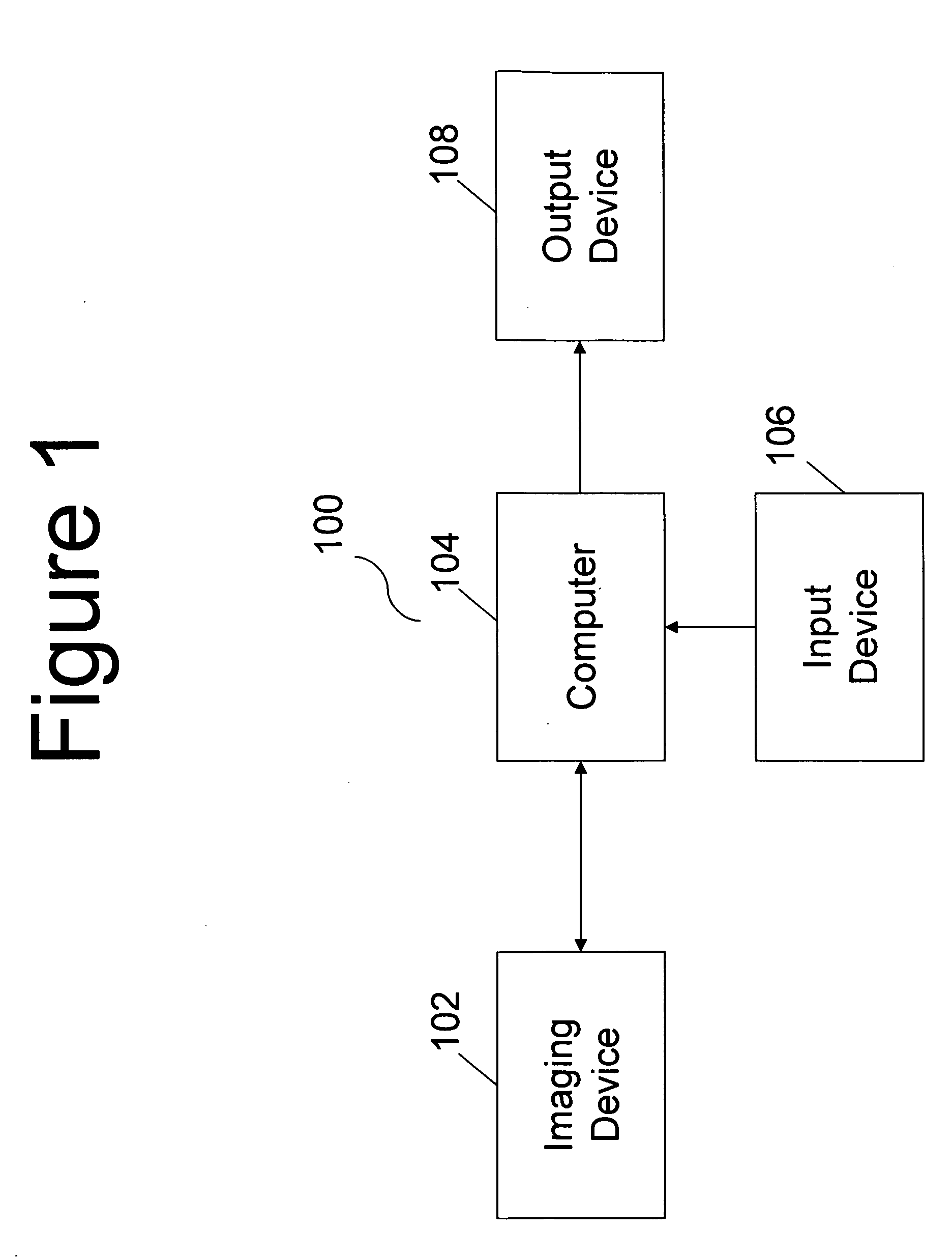
[0022]FIG. 1 is an example of one of many embodiments of the present invention. The imaging system of FIG. 1 consists of an imaging device 102, computer 104, input device 106, and output device 108. The imaging device 102 is used for capturing two dimensional images, and subsequently creating two dimensional image data. This two dimensional image data is then converted to a three dimensional images by using a computer 104 with software. The user through the use of input devices 106 may then view the three dimensional images from a multitude of viewing angles, and has the ability to immerse the viewing points from within the three dimensional image. These three dimensional images are then sequentially choreographed to create a fly through sequence of the images. This sequence is then displayed through an output device 108 that is attached ...


PUM


Abstract

This is an imaging system configured and optimized for capturing two dimensional images of a desired section of body tissue and converting these images into three dimensional virtual environment images. These three dimensional virtual environment images are then viewed at multiple immersive omnidirectional viewing angles. The viewing angles are then choreographed into a desired sequence to create a fly through sequence through the cellular layers of a desired section of body tissue.

Description

BACKGROUND OF THE INVENTION[0001]1. Field of the Invention[0002]The present invention relates to an imaging system, and more particularly, to an imaging system, which displays multiple viewing points and immersive omnidirectional viewing for a three dimensional fly through image of a cornea.[0003]2. Discussion of the Related Art[0004]Transparency, avascularity, and immunologic privilege make the cornea very difficult to examine. In a conventional imaging device, two dimensional images are used to create three dimensional images of the cornea. However, due to limitations associated with the processing of large amounts of two dimensional images into three dimensional images, and the transparent nature of the cornea, conventional three dimensional images of the cornea and other areas of the patient's body do not allow the viewer to view the images from multiple viewing points, as well as multiple viewing points wherein the viewer has the capability to immerse their viewing perspective ...

Claims


Application Information

Patent Timeline
Patent Type & Authority Applications(United States)
IPC IPC(8): H04N13/00H04N5/225
CPCA61B5/0068A61B5/0073A61B5/0536A61B6/03A61B6/506H04N13/0011H04N13/0275A61B6/4092A61B8/14H04N13/111H04N13/275
Inventor WARING, IV, GEORGE O.
Owner WARING IV GEORGE O
Why Eureka
Try Eureka