Image processing device, projection system, and image processing method

a technology of image processing and projection system, applied in image enhancement, pulse technique, instruments, etc., can solve the problems of inability to reduce the size and weight of the projector, the internal configuration of the projector becomes complicated, and the image sharpness is reduced. , to achieve the effect of appropriate correction of image sharpness degradation

Inactive Publication Date: 2010-04-01
COLUMBIA PEAK VENTURES LLC
View PDF10 Cites 3 Cited by
  • Summary
  • Abstract
  • Description
  • Claims
  • Application Information

AI Technical Summary

Benefits of technology

[0016]Therefore, an advantage of some aspects of the invention is to provide an image processing device, a projection system, and an image processing method capable of appropriately correcting the degradation in sharpness of the image due to the pixel shift without using a mechanical positioning mechanism.

Problems solved by technology

Such pixel shift to the ideal pixel positions also causes degradation in sharpness of the image displayed on a screen as the projection surface.
However, since the technology disclosed in the Document 1 is for moving the light modulation element using a mechanical positioning mechanism, it is required to dispose the positioning mechanism with a complicated configuration inside the projector.
Therefore, the internal configuration of the projector becomes complicated, and further, downsizing and weight saving of the projector are inhibited.
Therefore, the adjustment using a mechanical positioning mechanism such as an actuator might substantially be difficult in some cases.

Method used


Image

  • Image processing device, projection system, and image processing method
  • Image processing device, projection system, and image processing method
  • Image processing device, projection system, and image processing method

Examples


first embodiment

[0050]The projection system 10 according to the first embodiment is a projection system in which the positions of the pixels of two projectors corresponding to each other are set so as to be shifted ½ pixel from each other in an oblique direction as shown in FIG. 9A.

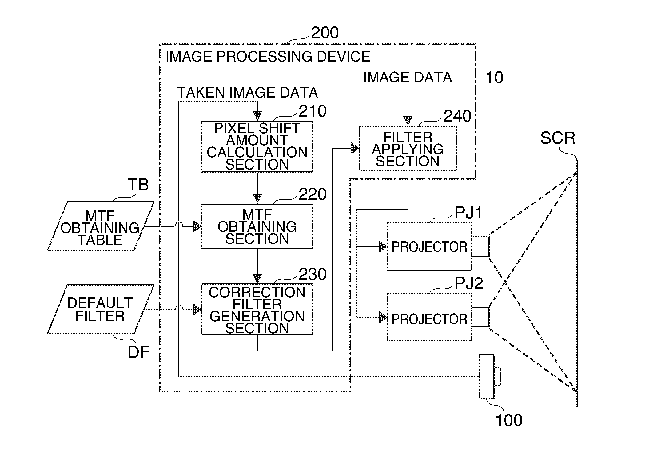
[0051]FIG. 1 is a diagram showing a configuration of the projection system 10 according to the first embodiment. As shown in FIG. 1, the projection system 10 according to the first embodiment is provided with two projectors PJ1, PJ2 for projecting an image on a screen SCR as a projection surface, an image taking device 100 for taking the image projected on the screen SCR, and an image processing device 200 for executing image processing for correcting the degradation of the sharpness based on the taken image data output from the image taking device 100.

[0052]The image processing device 200 is provided with a pixel shift amount calculation section 210 for calculating the pixel shift amount (r, θ) with respect to the ideal...

second embodiment

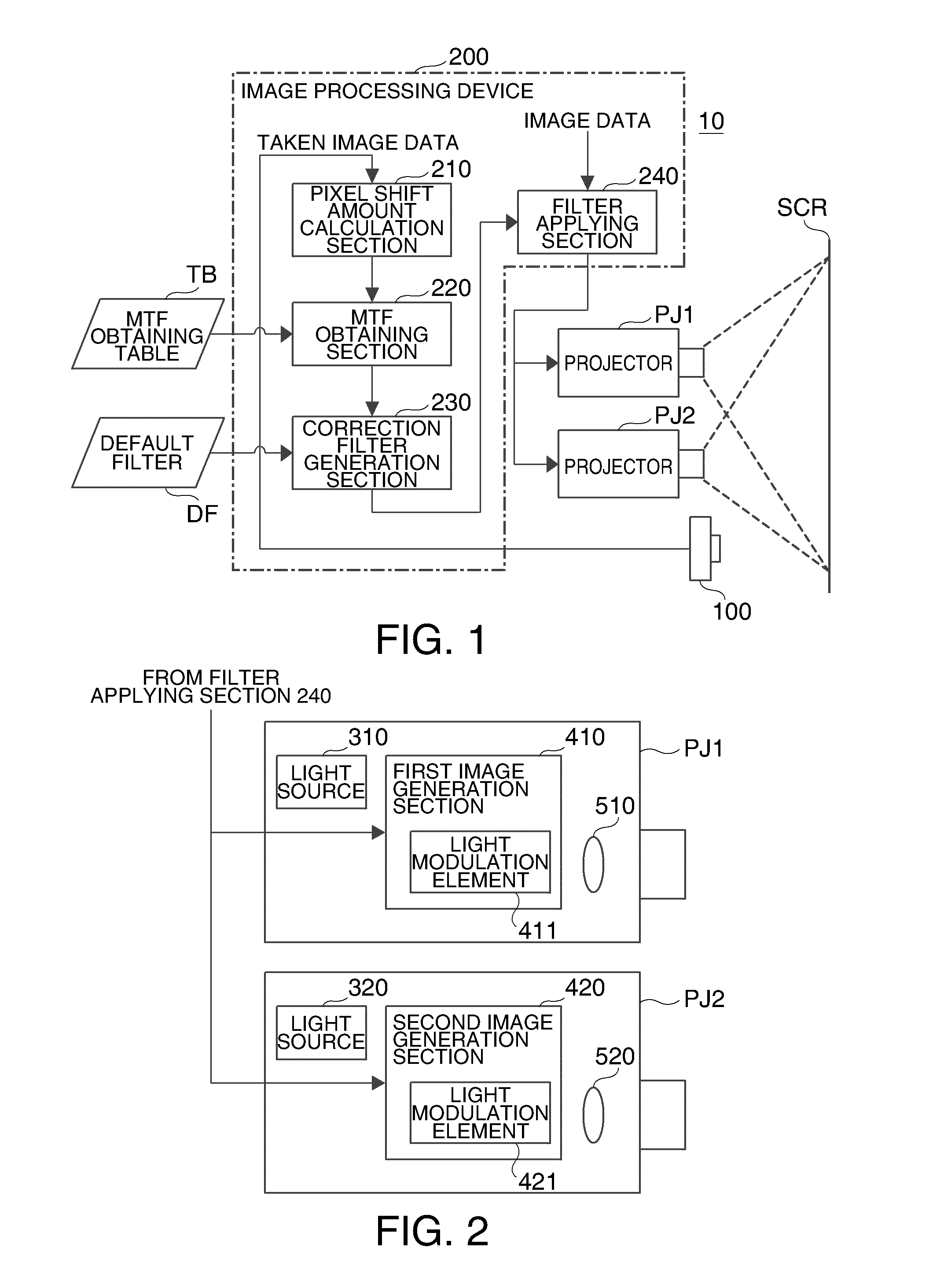
[0075]The projection system 20 according to the second embodiment is a projection system provided with one projector, and two image generation sections (a first image generation section and a second image generation section) are provided to the one projector. Further, the projection system 20 takes the state, in which the pixels of the light modulation element provided to the first image generation section and the pixels of the light modulation element provided to the second image generation section corresponding to each other are identical to each other or shifted a predetermined amount, as the ideal pixel positions, and displays the images generated respectively by the first image generation section and the second image generation section so as to overlap with each other on the screen SCR.

[0076]FIG. 7 is a diagram showing a configuration of the projection system 20 according to the second embodiment. As shown in FIG. 7, the projection system 20 according to the second embodiment i...


PUM


Abstract

An image processing device in a projection system that includes a first image generation section adapted to project first image on a projection surface and a second image generation section adapted to project second image on the projection surface so as to overlap the first image is disclosed. The image processing device includes: a pixel shift amount calculation section adapted to calculate a pixel shift amount between the first image and the second image; a modulation transfer function (MTF) obtaining section adapted to obtain MTF at a predetermined frequency, corresponding to the pixel shift amount calculated by the pixel shift amount calculation section; a correction filter generation section adapted to generate a correction filter adapted to correct the MTF so that the image displayed on the projection surface has desired sharpness; and a filter applying section adapted to apply the correction filter to image data corresponding to the image.

Description

BACKGROUND[0001]1. Technical Field[0002]The present invention relates to a projection system for projecting a plurality of images in a condition in which positions of corresponding pixels of the images are identical to each other or shifted a predetermined amount from each other, an image processing device, and an image processing method in such a projection system.[0003]2. Related Art[0004]There is known a projection system for projecting a plurality of images in a condition in which positions of corresponding pixels of the images are identical to each other or shifted a predetermined amount from each other. In such a projection system, it is possible to achieve higher resolution of the image displayed on a projection surface by, for example, projecting images respectively from a plurality of projectors (two projectors are assumed here only for the sake of simplicity of explanations), while setting the positions of the corresponding pixels of the two projectors so as to be shifted ...

Claims


Application Information

Patent Timeline
Patent Type & Authority Applications(United States)
IPC IPC(8): H04N3/26
CPCH04N9/3147H04N9/3188G06T5/20G06T5/003H04N9/3197
Inventor SAIGO, MANABU
Owner COLUMBIA PEAK VENTURES LLC
Why Eureka
Try Eureka