Transparent shock-absorbing laminate and flat panel display using the same

a technology of shock-absorbing laminate and flat panel display, which is applied in the direction of identification means, instruments, seals, etc., can solve the problems of increased reflectance, thin and fragile glass substrates used in pdps, and insufficient shatterproofness, etc., to reduce the impact force

Inactive Publication Date: 2002-02-28
NITTO DENKO CORP
View PDF0 Cites 69 Cited by
  • Summary
  • Abstract
  • Description
  • Claims
  • Application Information

AI Technical Summary

Benefits of technology

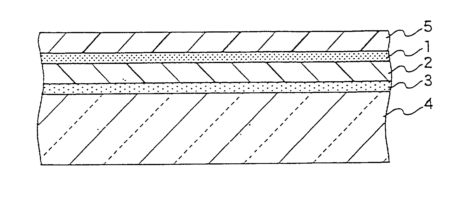
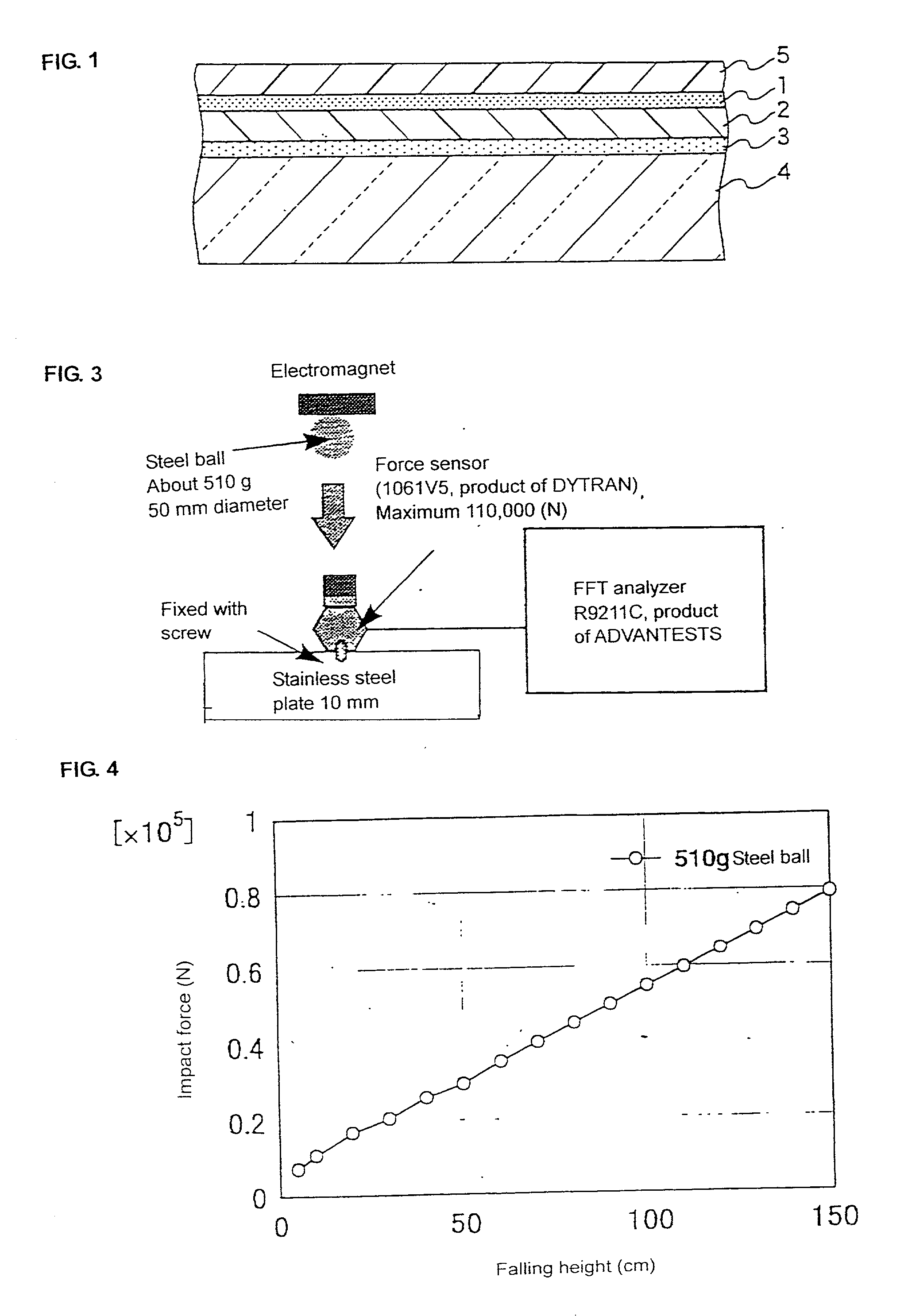
0078] In addition to the known standards for shatterproofness and safety against an electrical shock, guidelines for designing a shock-absorbing laminate that will protect a glass panel against fracture have now been made clear by determining the actual impact force of a steel ball weighing 510 g dropped from a height of 1.5 m with which a glass substrate is fractured and by constituting

Problems solved by technology

These glass panels are characterized by their shatterproofness but are not protected against breakage.
PDPs have been attracting attention for their wide screen, but the glass substrate used in PDPs are particularly thin and fragile.
Because of the space between the glass panel and the protective filter, there are left many problems, such as double reflection of external light, an increase of reflectance, and reduction

Method used


Image

  • Transparent shock-absorbing laminate and flat panel display using the same
  • Transparent shock-absorbing laminate and flat panel display using the same
  • Transparent shock-absorbing laminate and flat panel display using the same

Examples


example 2

[0106] A glass substrate with a shock-absorbing laminate was prepared in the same manner as in Example 1, except for changing the thickness of the fracture-proof layer 2 (PP / EVA / PP laminate, POVIC-T) to 600 .mu.m. The thickness of the shock-absorbing laminate (PET / pressure-sensitive adhesive layer / POVIC-T / adhesive layer) was 825 .mu.m. and the glass substrate with a shock-absorbing laminate had a transmission of 80%.

example 3

[0107] A glass substrate with a shock-absorbing laminate was prepared in the same manner as in Example 1, except for replacing the fracture-proof layer 2 with a 500 .mu.m thick polyurethane film (DUS605, non-yellowing type, available from Seadam Co; shearing modulus: 4.6.times.10.sup.7 Pa). The thickness of the shock-absorbing laminate (PET / pressure-sensitive adhesive layer / urethane / pressure-sensitive adhesive layer) was 625 .mu.m, and the glass substrate with a shock-absorbing structure had a transmission of 78%.

example 4

[0108] A glass substrate with a shock-absorbing laminate was prepared in the same manner as in Example 1, except for replacing the PP / EVA / PP laminate with a 400 .mu.m thick ClearTec H film (a film of PP blended with a styrene-vinyl-isoprene elastomer, supplied by Kuraray Trading Co.; shearing modulus: 3.1.times.10.sup.7 Pa) as the fracture-proof layer 2. The thickness of the shockabsorbing laminate (PET / pressure-sensitive adhesive layer / CleaTec H / pressure-sensitive adhesive layer) was 625 .mu.m, and the glass substrate with a shock-absorbing laminate had a transmission of 72%.


PUM

PropertyMeasurementUnit
Fractionaaaaaaaaaa
Thicknessaaaaaaaaaa
Forceaaaaaaaaaa

Abstract

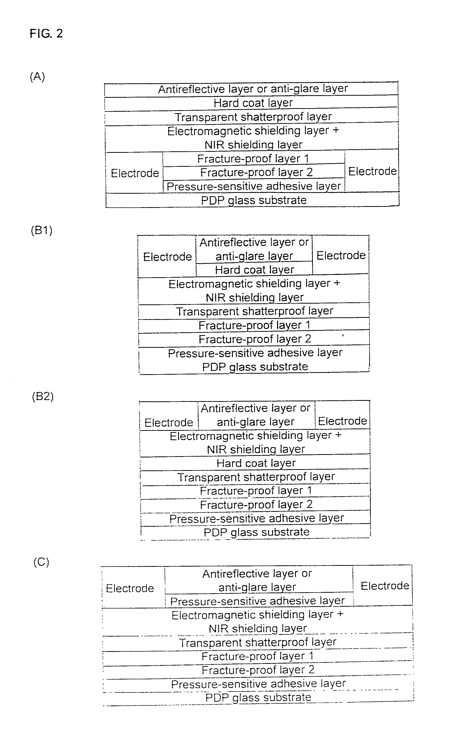
A transparent shock-absorbing laminate to be formed on a glass substrate for a display panel having a fracture strength such that it is fractured by a falling ball impact (drop height: 1.5 m; ball weight: 510 g) corresponding to 79,000 N, the transparent shock-absorbing laminate comprising a shatterproof layer having a shearing modulus of 2x10⁸ Pa or more, at least two fracture-proof layers having a shearing modulus ranging from 1x10⁴ to 2x10⁸ Pa, each having different modulus, and a transparent pressure-sensitive adhesive layer.

Description

[0001] This invention relates to a transparent shock-absorbing laminate and a flat panel display using the same, More particularly, it relates to a shatterproof and fracture-proof shock-absorbing laminate which is to be formed on a glass substrate of a flat panel display, especially a glass substrate of a plasma display panel.[0002] Glass cathode-ray tubes (CRT) for TV sets and other =displays are required to be shatterproof and not to allow a falling steel ball to pierce and make a hole of finger size or greater (which may give an electric shock) in a falling ball test as regulated by safety standards (e.g., UL Standards and Electrical Appliance and Material Control Law, Japan). To meet these standards the CRT glass panel should have some thickness.[0003] In order to achieve weight reduction while securing shatterproofness, CRT glass panels laminated with a self-repairing synthetic resin protective film (preferably a thermosetting urethane resin film) have been proposed in JP-A-6-3...

Claims


Application Information

Patent Timeline
IPC IPC(8): B32B17/10B32B27/08
CPCB32B17/10018B32B17/10174B32B17/10366B32B27/08Y10T428/2848H01J2329/86Y10S428/911Y10T428/28H01J2211/34Y10T428/31649Y10T428/31645Y10T428/31641Y10T428/31786Y10T428/31616
Inventor HIEDA, YOSHIHIROMIYAUCHI, KAZUHIKONAKAMURA, TOSHITAKAAZUMI, YUKIKO
Owner NITTO DENKO CORP
Why Eureka
Try Eureka