Spatial light modulator performing a gamma correction

Inactive Publication Date: 2010-04-01
SILICON QUEST KABUSHIKI KAISHA +1
View PDF12 Cites 5 Cited by
  • Summary
  • Abstract
  • Description
  • Claims
  • Application Information

AI Technical Summary

Benefits of technology

[0033]In consideration of the situation as described above, the present invention aims at providing a spatial light modulator (SLM) and a control apparatus therefor, which are enabled to correct the input / output characteristic of a video image displaying without depending on a circuit scale and a process capability and to display a video image allowing no degradation in the number of gray scale level against that of the input data.

Problems solved by technology

Although significant advances have been made in technologies of implementing electromechanical micro-mirror devices as spatial light modulators, there are still limitations in their high quality images display.
Specifically, when display images are digitally controlled, image quality is adversely due to an insufficient number of gray scales.
The quality of an image display is limited due to the limited number of gray scales.
Since the mirror is controlled to operate in an either ON or OFF state, the conventional image display apparatuses have no way to provide a pulse width to control the mirror that is shorter than the control duration allowable according to the LSB.
The limited gray scale due to the LSB limitation leads to a degradation of the quality of the display image.
This method, using an exponential or logarithmic conversion or a polynomial expression to convert an input signal, depends highly on the process capability of a device and has a low degree of freedom in the arithmetic expression in order to carry out an accurate correction in response to the displaying speed, and therefore it is very difficult to attain a complex characteristic on the basis of a user's setup.
On the other hand, the method is faced with a problem that the scale of the table grows with the number of pixels of video images in recent years, requiring a vast memory space particularly in the case of having the setup information of a plurality of display modes and accordingly increasing the scale of the circuit.
Meanwhile, when the word of digital data is converted, and if the conversion is carried out so as to obtain nonlinear output data for each value of the input data that is capable of containing, for example, 1024 pieces (i.e., 10 bits) of information, a part of values included in the input data will be lost.
This in turn means that the gray scale levels included in the input data cannot be displayed correctly, and therefore the gray scale level is degraded.

Method used


Image

  • Spatial light modulator performing a gamma correction
  • Spatial light modulator performing a gamma correction
  • Spatial light modulator performing a gamma correction

Examples


Embodiment Construction

[0081]Preferred embodiments according to the present invention are described in the following with reference to the accompanying drawings.

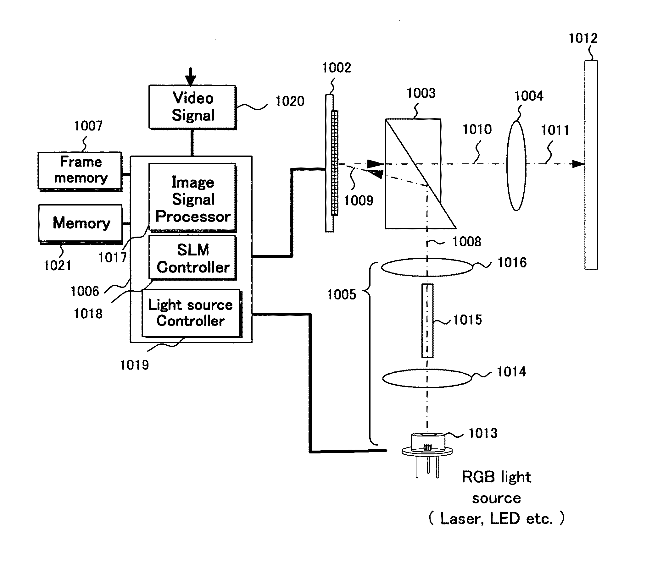
[0082]FIG. 3 is a diagram showing an exemplary comprisal of a display apparatus according to a preferred embodiment of the present invention.

[0083]As shown in FIG. 3, the display apparatus according to the present embodiment comprises a single spatial light modulator (noted as “SLM” hereinafter) 1002, a total internal reflection (TIR) prism 1003, a projection optical system 1004, a light source optical system 1005, a display processing unit 1006 and frame memory 1007. Here, the SLM 1002 is, for example, a mirror device comprising a plurality of micromirrors.

[0084]The SLM 1002 and TIR prism 1003 are place in the optical axis of the projection optical system 1004, and the light source optical system 1005 is placed in a manner so that the optical axis thereof is aligned with that of the projection optical system 1004.

[0085]The TIR prism 1003 has the ...


PUM


Abstract

An image projection system implemented with a spatial light modulator (SLM) comprises a plurality of pixel elements each includes a pixel memory wherein said SLM receives inputted bit data representing an image from an external image source to write the inputted data into said pixel memory wherein said SLM further adjusts a smallest period for displaying image represented by a least significant bit (LSB) of the inputted data.

Description

[0001]This application is a Non-Provisional Application of Application 61 / 195,853 and claims the Priority Date of Oct. 9, 2008. This Application is also a Continuation-in Part (CIP) Application of a co-pending Non-provisional application Ser. No. 11 / 818,119 filed on Jun. 29, 2007 and 12 / 004,607 filed on Dec. 24, 2007. application Ser. Nos. 11 / 818,119 and 12 / 004,607 are Continuation-in Part (CIP) Applications of a U.S. patent application Ser. No. 11 / 121,543 filed on May 4, 2005, now issued into U.S. Pat. No. 7,268,932. The application Ser. No. 11 / 121,543 is a Continuation in part (CIP) Application of three previously filed Applications. These three Applications are Ser. No. 10 / 698,620 filed on Nov. 1, 2003; Ser. No. 10 / 699,140 filed on Nov. 1, 2003, now issued into U.S. Pat. No. 6,862,127; and Ser. No. 10 / 699,143 filed on Nov. 1, 2003 now issued into U.S. Pat. No. 6,903,860 by one of the Applicants of this patent application. The disclosures made in these patent applications are here...

Claims


Application Information

Patent Timeline
IPC IPC(8): H04N9/31G02B26/00
CPCC07D213/85C07D401/12C07D401/14C07D413/14C07D405/14C07D409/14C07D403/14
Inventor ENDO, TAROMAEDA, YOSHIHIROSHIRAI, AKIRAISHII, FUSAO
Owner SILICON QUEST KABUSHIKI KAISHA
Why Eureka
Try Eureka