Planar light source device and display apparatus incorporating same

a technology of light source device and display device, which is applied in the direction of planar/plate-like light guide, lighting and heating apparatus, instruments, etc., can solve the problems of insufficient light diffusion, reduced light utilization efficiency, and inability to achieve uniform intensity distribution in some cases, and achieve high light utilization efficiency and high intensity. uniform

Inactive Publication Date: 2010-04-01
TRIVALE TECH LLC
View PDF20 Cites 90 Cited by
  • Summary
  • Abstract
  • Description
  • Claims
  • Application Information

AI Technical Summary

Benefits of technology

[0007]The object of the present invention is to provide a planar light source device with highly ...

Problems solved by technology

However, light intensity at a portion of the above cone-shaped recess can be higher than that at the rest of portions, so that uniformities of intensity distribution cannot in some cases be achieved.
However, a problem with such a planar light source device as disclosed in Patent Document 2 is that light emitted toward the front of the light source is mostly absorbed by the light reflective surface, thus resulting in reduction in light utilization efficiency.
However, a problem with such a liquid crystal display device as disclosed in Patent Document 3 is that although direct ...

Method used


Image

  • Planar light source device and display apparatus incorporating same
  • Planar light source device and display apparatus incorporating same
  • Planar light source device and display apparatus incorporating same

Examples


embodiment 1

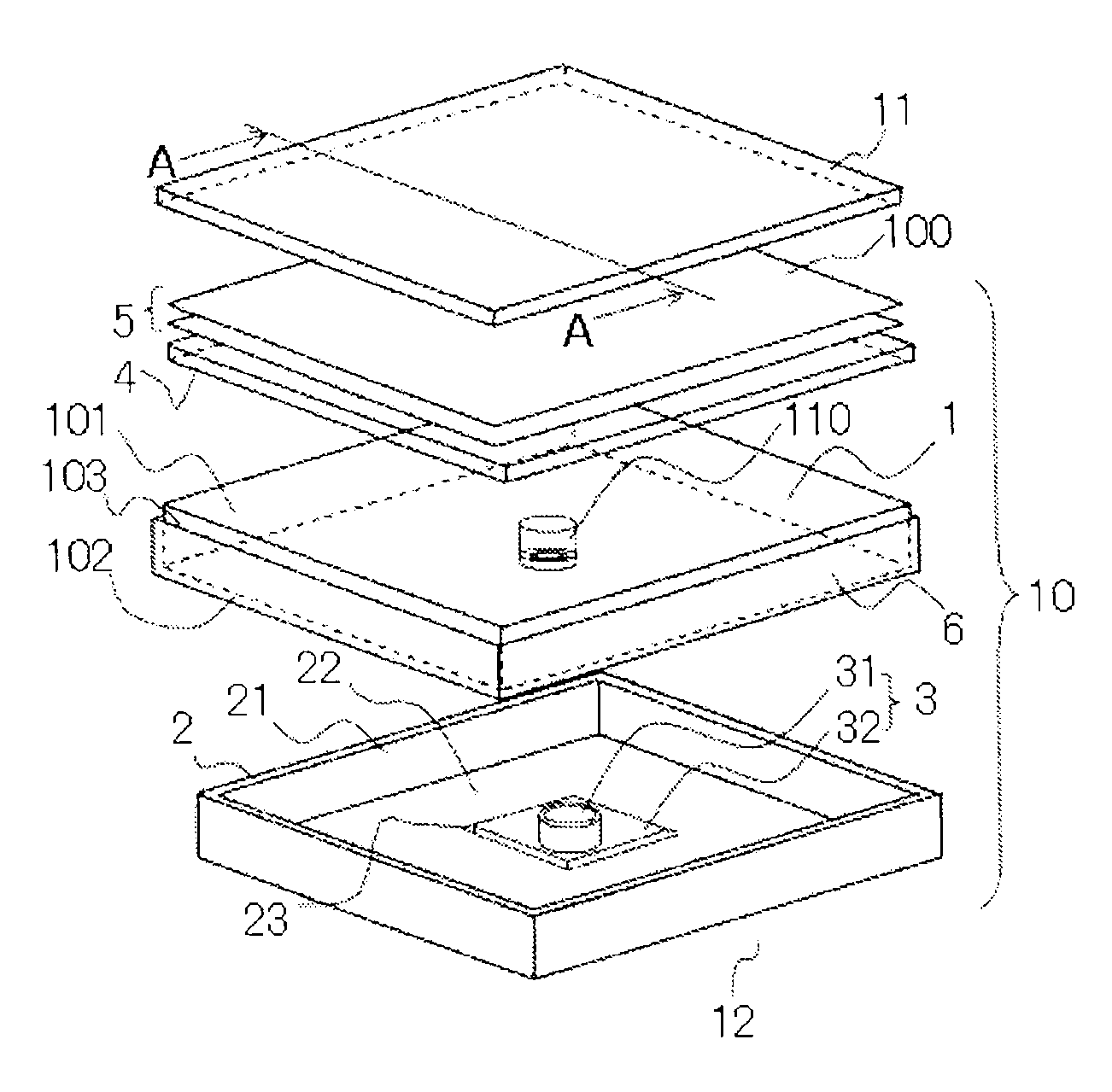
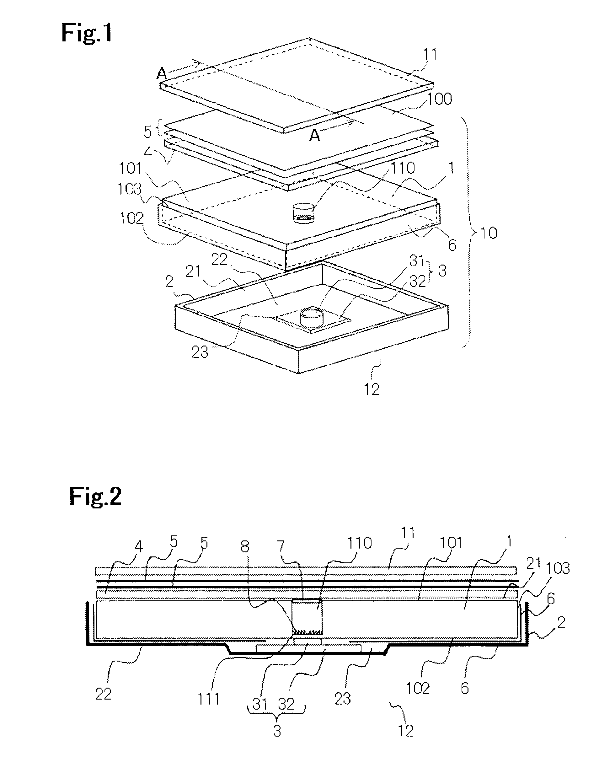
[0034]FIG. 1 is an exploded perspective view of a display device according to the present embodiment; FIG. 2 is a cross sectional view taken along the line A-A of the FIG. 1 with the display device of FIG. 1 assembled. As shown in FIGS. 1 and 2, a planar light source device 10 according to Embodiment 1 includes a light guide plate 1 for guiding light, across the planar area of the light guide plate, to emit it from an exit surface 101 as a surface emitting light; the light guide plate is disposed within a housing having an opening 21. Further, a light source 3 is placed in a recessed space 23 formed on an inside bottom 22 of the housing 2; on a place located toward the exit surface 101 of the light guide plate 1 are disposed a diffuser plate 4 and an optical sheet 5. A reflective sheet 6 for reflecting light is provided on an opposite surface 102, which is a surface located opposite the exit surface 101 of the light guide plate 1, and on sides 103 of the light guide plate. On such t...

embodiment 2

[0063]FIG. 10 shows a cross section of a planar light source device according to Embodiment 2; FIG. 11 shows an enlarged view of the chief part of the device. In Embodiment 1, the exit surface 101 of the light guide plate 1 is formed with the first recess 110, and the light source 3 is disposed so as to face the opposite surface 102 of the light guide plate 1, while in Embodiment 2, as shown in FIG. 10, on the opposite surface 102 is provided a second recess 120 (numeral 120 shown in FIG. 11) that is located opposite the first recess 110 of the light guide plate 1 where the light source 3 is accommodated. The configuration other than what is described above is the same as that in Embodiment 1. An advantage similar to that of the planar light source device according to Embodiment 1 is also achieved except the special advantageous feature associated with the planar light source device according to Embodiment 2, as will be described below.

[0064]The path of light having emitted from the...

embodiment 3

[0068]FIG. 12 shows an enlarged view of the chief part of a planar light source device according to Embodiment 3. The planar light source device according to Embodiment 3 has a convexed portion 123 extending toward an opening 124 formed on the bottom 121 of the second recess 120. Here, the rest of the configuration other than that of providing the convexed portion 123 is the same as that in Embodiment 2. An advantage similar to the planar light source device according to Embodiment 1 and Embodiment 2 is achieved except the advantageous feature associated with the planar light source device according to the present embodiment, as will be described below.

[0069]Next, FIG. 13 shows an enlarged view of the chief part of the convexed portion 123 formed in the light guide plate. As shown in FIG. 13, the convexed portion 123 is formed integral with the bottom 121 of the second recess 120. The convexed portion 123 represents a convex lens whose center portion extends toward the opening 124 o...


PUM


Abstract

A planar light source device with highly uniform intensity and high light utilization efficiency, and a display apparatus incorporating the same, are provided. A light guide plate, configured by a material such as plate-shaped and transparent acryl resin, polycarbonate resin, or glass, causes incident light to propagate within the light guide plate and then to exit the light through an exit surface as a surface emitting light. A first recess is formed substantially in the center of the exit surface. The first recess is cylinder-shaped, and on a bottom thereof is provided a lens that refracts incident light from a light source, in a direction away from the center of a circle on the bottom.

Description

BACKGROUND OF THE INVENTION[0001]1. Field of the Invention[0002]The present invention relates to a planar light source device from which light is shined on the rear or back side of a display element such as a liquid crystal display, and to a display apparatus incorporating the same.[0003]2. Description of the Related Art[0004]As disclosed in, for example, Japanese Patent No. 3427636 (hereinafter called Patent Document 1), a conventional planar light source device is provided with a cone-shaped recess having a triangular cross section at the rear center of a light guide plate, in which recess a light source is disposed. In such a planar light source device as disclosed in Patent Document 1, the amount of light is small toward the front of the light source. However, light intensity at a portion of the above cone-shaped recess can be higher than that at the rest of portions, so that uniformities of intensity distribution cannot in some cases be achieved.[0005]Furthermore, a planar ligh...

Claims


Application Information

Patent Timeline
IPC IPC(8): G02F1/13357F21V3/00F21V7/00
CPCG02B6/0016G02B6/0021G02B6/0091G02F1/133603G02F1/133611G02B6/0031
Inventor SAKAI, SEIJI
Owner TRIVALE TECH LLC
Why Eureka
Try Eureka