Vehicle interior lighting device

a technology for interior lighting and vehicles, applied in interior lighting, transportation and packaging, lighting and heating equipment, etc., can solve the problems of not being able to output different illumination patterns of light according to different areas, and achieve the effects of reducing the number of light sources installed, low light loss, and high light consumption

Inactive Publication Date: 2010-04-01
TOYODA GOSEI CO LTD
View PDF1 Cites 19 Cited by
  • Summary
  • Abstract
  • Description
  • Claims
  • Application Information

AI Technical Summary

Benefits of technology

[0022]A vehicle interior lighting device according to one embodiment of the invention is constructed such that a notch with relatively low light loss is disposed at a light input side of a rod-shaped light guiding member near a light source, and a grain finish portion with relatively high light consumption is disposed at a light output side of the rod-shaped light guiding member far from the light source. Therefore, the amount of light will not be short at the grain finish portion. In addition, the pinpoint light radiation (or illumination) by using the notch reflection can be conducted together with the wide range light radiation (or illumination) by using the grain finish portion scattering. Furthermore, the plural areas can be illuminated by only one light source with different illumination patterns according to the areas so as to reduce the number of the light source installed in the vehicle to lower the production cost.

Problems solved by technology

However, the lighting device of JP-A-2007-179962 has a problem that it can only output a same illumination pattern of light along the axis direction of the light guiding member and, therefore, it is impossible to output different illumination patterns of light according to different areas.

Method used


Image

  • Vehicle interior lighting device
  • Vehicle interior lighting device
  • Vehicle interior lighting device

Examples


Embodiment Construction

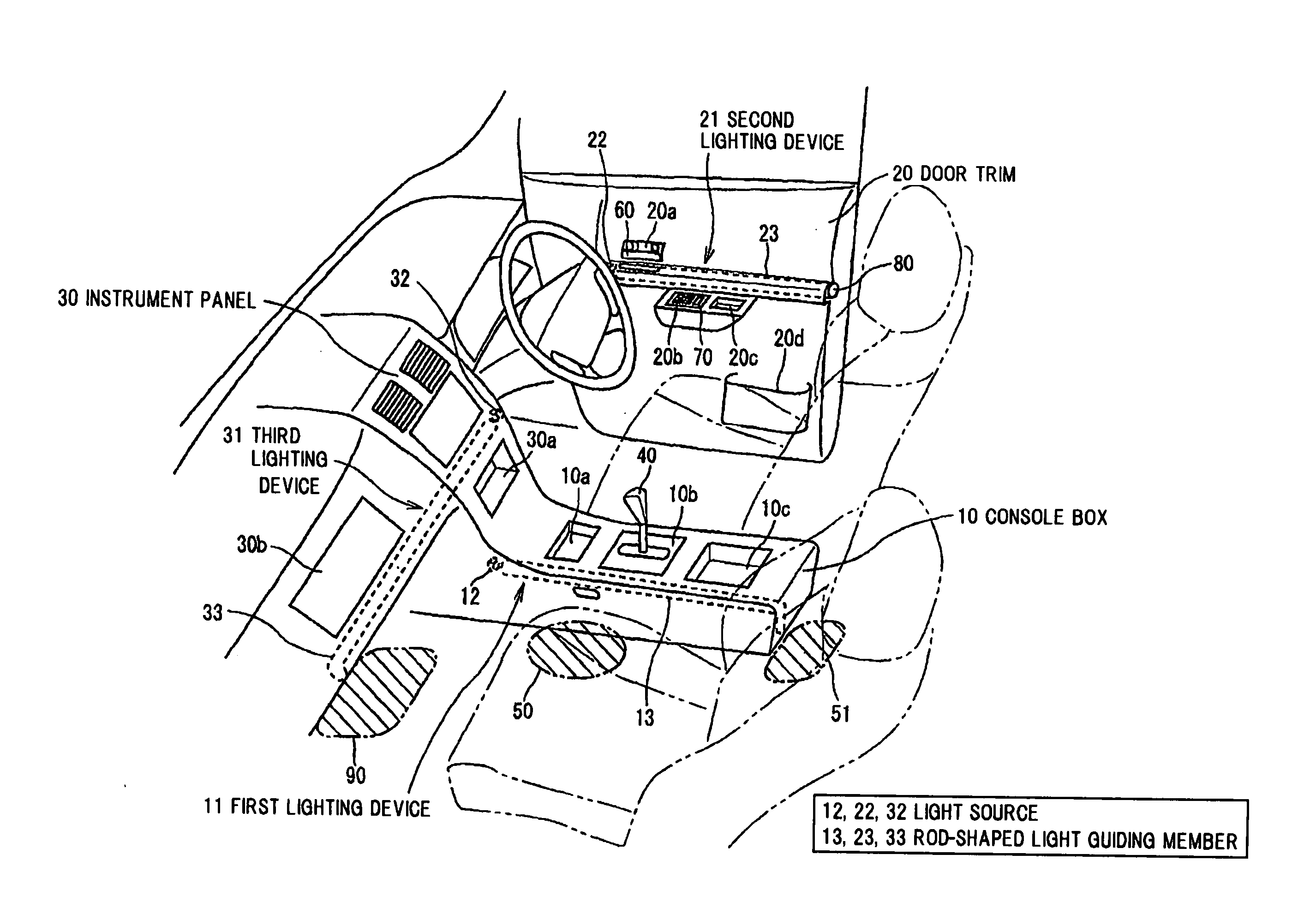
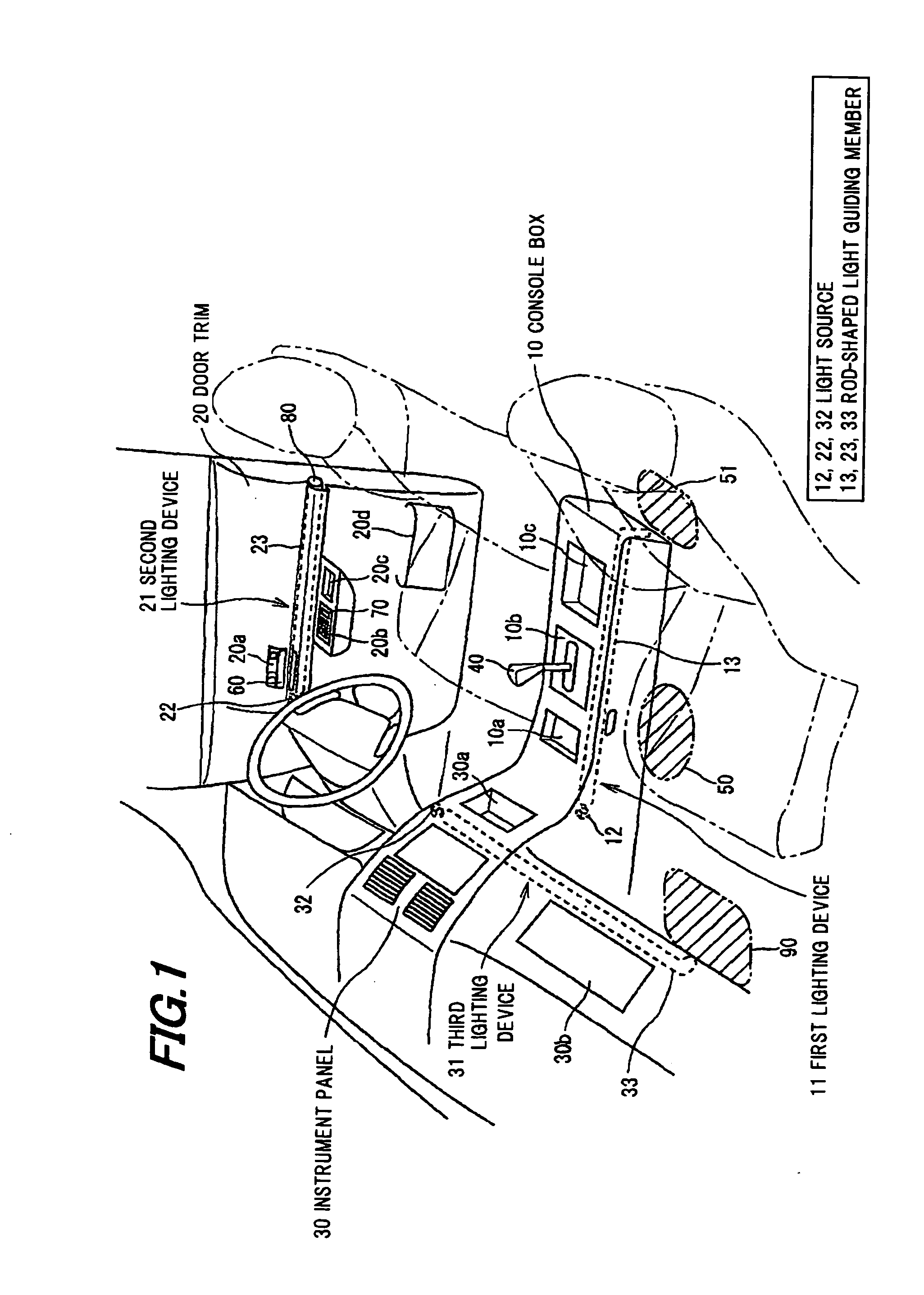
[0033]FIGS. 1 to 8 show one embodiment of the invention. FIG. 1 is a perspective view showing a vehicle interior provided with a vehicle interior lighting device in a preferred embodiment according to the invention.

[0034]As shown in FIG. 1, the vehicle interior is provided with a console box 10 disposed between a driver seat and a passenger seat, a door trim 20 on the interior side of the vehicle door, and an instrument panel 30 disposed on the front side of the interior. The first lighting device 11 is installed in the console box 10, the second lighting device 21 is installed in the door trim 20, and the third lighting device 31 is installed in the instrument panel 30. The lighting devices 11, 21 and 31 are adapted to illuminate plural areas by light sources 12, 22 and 32, respectively.

[0035]The console box 10 is provided with a concave change box 10a, a shift panel 10b for indicating the positions of a shift lever 40, and a concave box main body 10c, which are disposed sequential...


PUM


Abstract

A vehicle interior lighting device includes a light source disposed in a vehicle, and a rod-shaped light guiding member including an one end face through which light emitted from the light source is inputted a transparent material, and a transparent material for guiding the inputted light from the one end face to an other end in an axis direction of the rod-shaped light guiding member. The rod-shaped light guiding member includes a first light radiation section for radiating light in a direction perpendicular to the axis direction according to a first illumination pattern to illuminate a first irradiated area in the vehicle, and a second light radiation section for radiating light in the direction perpendicular to the axis direction according to a second illumination pattern different from the first illumination pattern to illuminate a second irradiated area in the vehicle.

Description

[0001]The present application is based on Japanese patent application No. 2008-251891 filed on Sep. 29, 2008, the entire contents of which are incorporated herein by reference.BACKGROUND OF THE INVENTION[0002]1. Field of the Invention[0003]This invention relates to a vehicle interior lighting device for lighting different interior areas of a vehicle.[0004]2. Description of the Related Art[0005]A light device is known which comprises a light source, and a rod-shaped light guiding member extending in the light emission direction of the light source and having an upper face as a reflecting surface and a lower face as a light emission surface (See e.g., JP-A-2007-179962). The light device is constructed such that the reflecting surface of the rod-shaped light guiding member is provided with light reflecting grooves at predetermined intervals in the extending direction of the rod-shaped light guiding member and, of the light reflecting grooves, a light reflecting groove near the light so...

Claims


Application Information

Patent Timeline
Patent Type & Authority Applications(United States)
IPC IPC(8): B60Q1/26F21W106/00
CPCB60Q3/005B60Q3/0279B60Q3/0209B60Q3/74B60Q3/66B60Q3/20B60Q3/217B60Q2500/30
Inventor MARUI, YUKIKOINAGAKI, SATOSHI
Owner TOYODA GOSEI CO LTD
Why Eureka
Try Eureka