

Ultrasonic diagnostic apparatus
a diagnostic apparatus and ultrasonic technology, applied in the field of ultrasonic diagnostic apparatus, can solve the problem of conventionally difficult to observe only how a contrast medium is applied
- Summary
- Abstract
- Description
- Claims
- Application Information
AI Technical Summary
Benefits of technology
Problems solved by technology
Method used
Image

Examples
first embodiment
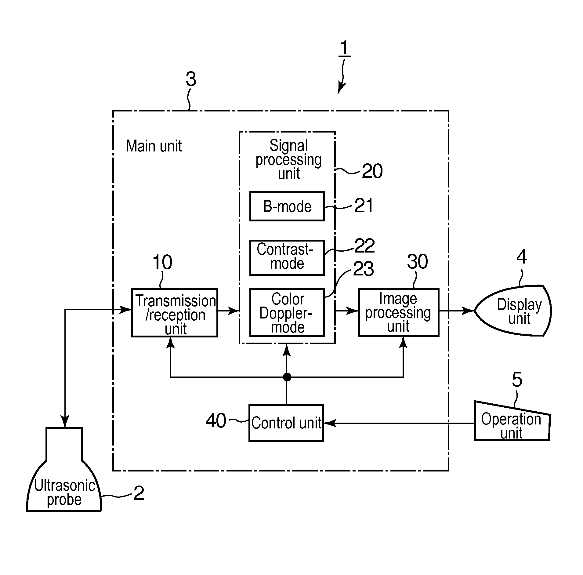
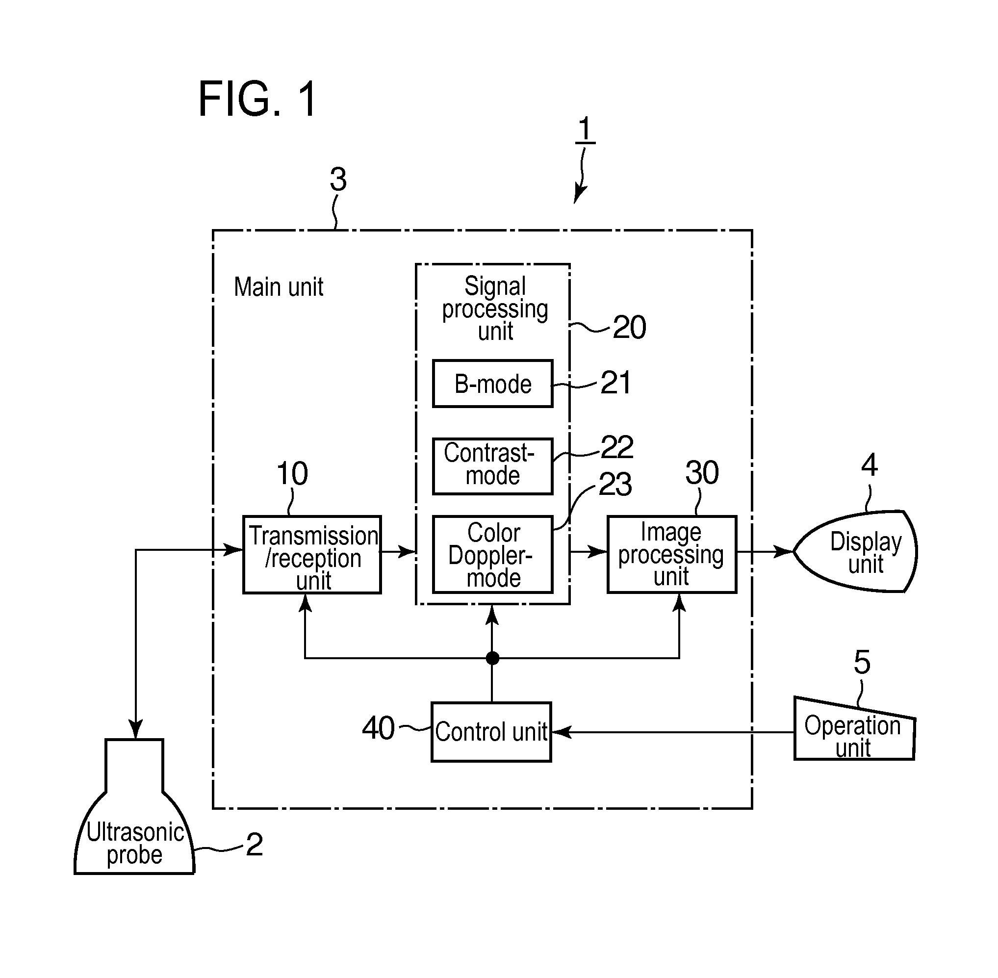
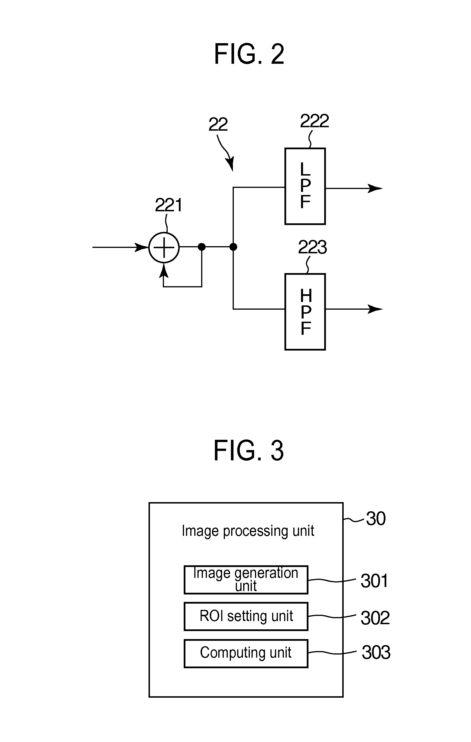
[0043]First, description will be given to a first embodiment of the invention. FIG. 1 is a block diagram illustrating the configuration of an ultrasonic diagnostic apparatus in an example of embodiments of the invention; FIG. 2 is a block diagram illustrating the configuration of the contrast-mode processing unit in the ultrasonic diagnostic apparatus illustrated in FIG. 1; and FIG. 3 is a block diagram illustrating the configuration of the image processing unit in the ultrasonic diagnostic apparatus illustrated in FIG. 1.
[0044]The ultrasonic diagnostic apparatus 1 in this example includes: an ultrasonic probe 2 that transmits and receives ultrasonic waves; an apparatus main unit 3; a display unit 4 that displays an ultrasonic image and the like; and an operation unit 5 including a keyboard, a pointing device, and the like. The display unit 4 is an example of display device in embodiments of the invention.
[0045]The apparatus main unit 3 includes: a transmission / reception unit 10 tha...
second embodiment
[0067]Description will be given to a second embodiment of the invention. FIG. 9 is a schematic diagram illustrating signal processing systems in ultrasonic imaging in the second embodiment. In the second embodiment, an ordinary B-mode image is displayed over a contrast-mode image in the above-mentioned contrast mode. In FIG. 9, a denotes a signal processing system for contrast mode and β denotes a signal processing system for B mode. With the signal processing system a for contrast mode, a fundamental image and a harmonic image are obtained similarly with the foregoing. With the signal processing system β for B mode, a monochrome B-mode image is obtained. A fundamental image, a harmonic image, and a B-mode image obtained with the individual signal processing systems α, 13 are combined at the combination unit 3013 and the ultrasonic image obtained as the result of this synthesis is displayed in the display unit 4. Since this synthetic image includes a B-mode image, it is possible to ...
third embodiment
[0070]Description will be given to a third embodiment of the invention. FIG. 10 is a schematic diagram illustrating signal processing systems and the like in ultrasonic imaging in the third embodiment. In the third embodiment, an image of blood flow information in color Doppler mode is also overlaid and displayed in addition to a contrast-mode image in contrast mode and an ordinary B-mode image. In FIG. 10, α denotes a signal processing system for contrast mode; β denotes a signal processing system for B mode; and γ denotes a signal processing system for color Doppler mode. A publicly known system can be used for the signal processing system γ for color Doppler mode and the drawing illustrates the configuration of an example of such a system. In the signal processing system γ for color Doppler mode, the color Doppler-mode processing unit 23 includes: a quadrature detection unit 231 that carries out reception and detection on the orthogonal I- and Q-axis components of multiple echo s...
PUM
 Abstract
Description
Claims
Application Information