Apparatus and method for measuring pulse waves

a pulse wave and apparatus technology, applied in the field of biological signal wave measurement, can solve problems such as the inability to correctly detect arrhythmias

Inactive Publication Date: 2010-04-01
TDK CORPARATION
View PDF6 Cites 24 Cited by
  • Summary
  • Abstract
  • Description
  • Claims
  • Application Information

AI Technical Summary

Problems solved by technology

Accordingly, the arrhythmia

Method used


Image

  • Apparatus and method for measuring pulse waves
  • Apparatus and method for measuring pulse waves
  • Apparatus and method for measuring pulse waves

Examples


first embodiment

The First Embodiment

[0027]With regard to a measurement apparatus of the first embodiment, a sensor to detect a pulse wave as biological information of a subject (a user) calculates pulse wave interval data, and decides whether a pulse waveform of each pulse is the arrhythmia. Pulse wave interval data acquired from the pulse wave not decided as the arrhythmia are stored as regular data. On the other hand, another data are stored as arrhythmia data.

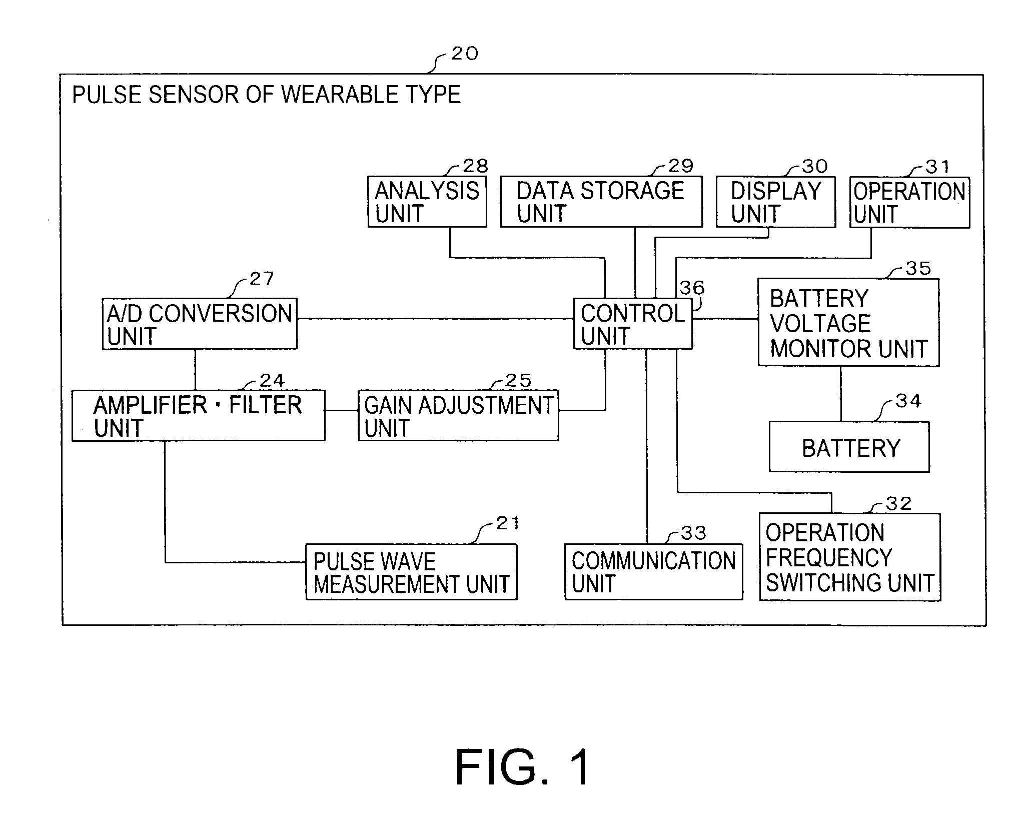
[0028]FIG. 1 is a block diagram of the measurement apparatus of the first embodiment. As the measurement apparatus, a pulse sensor 20 of wearable type is explained. Hereinafter, the pulse sensor of wearable type is called “a pulse sensor”. First, component of the pulse sensor 20 is explained.

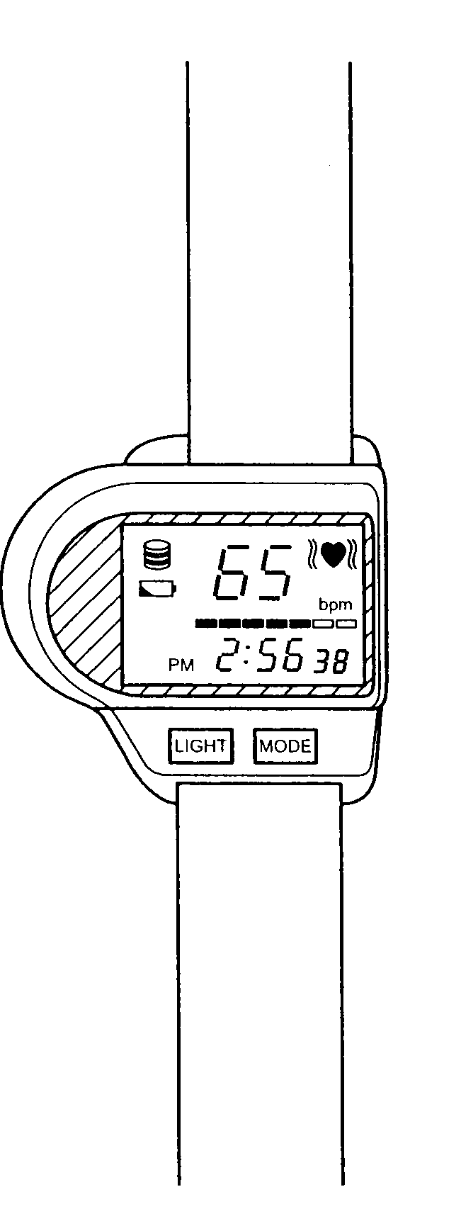
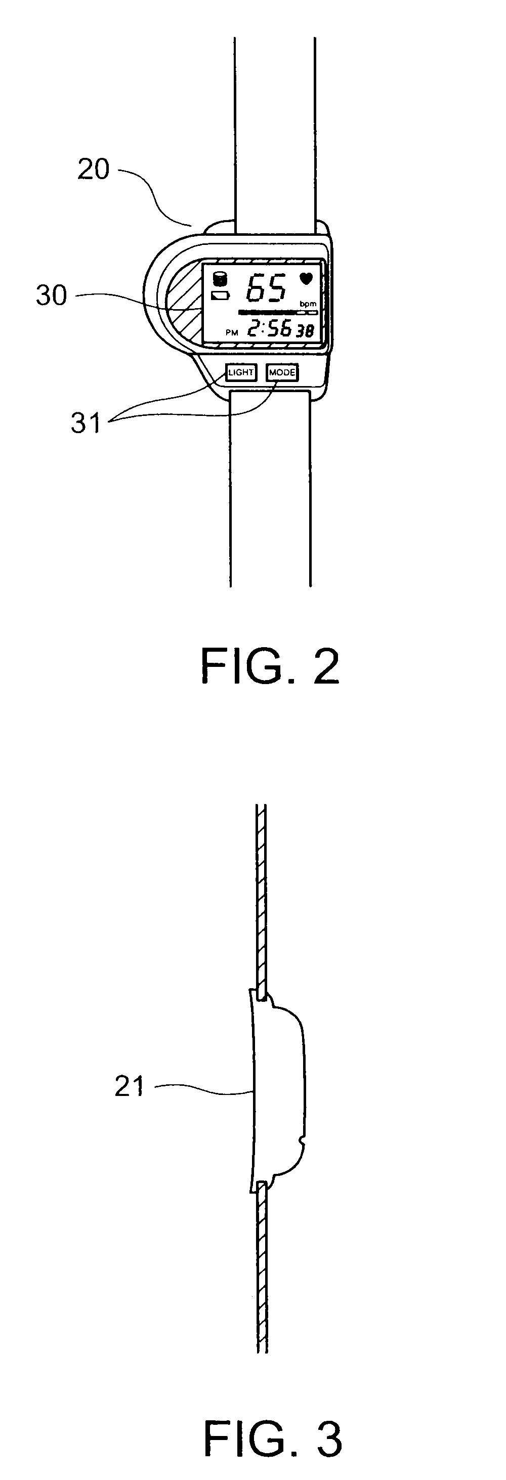
[0029]FIGS. 2 and 3 show one example of appearance of the pulse sensor 20. FIG. 2 is a plan and FIG. 3 is a side view of the pulse sensor 20. The pulse sensor 20 has a shape worn by a wrist (such as a wristwatch). As shown in FIG. 2, a display unit 30 a...

second embodiment

The Second Embodiment

[0054]In the first embodiment, the pulse sensor 20 having the pulse wave sensor 21 and the acceleration sensor 26 is explained. On the other hand, in the measurement apparatus of the second embodiment, instead of the pulse sensor 20, a mat sensor detecting a heartbeat and a body motion is explained. Briefly, in the second embodiment, a mat sensor as a sensor module of mat type is used. By measuring a vibration of the breast or the belly of a subject, the heartbeat and the body motion is detected during the subject is sleeping.

[0055]FIG. 11 is a schematic diagram of location example of the mat sensor. The mat sensor is connected to a pressure measurement unit 1161 located on the surface of a mattress 1128 of a bed 1127.

[0056]The pressure measurement unit 1161 detects non-existence, existence on the bed, and body motion of the subject. The pressure measurement unit 1161 is located at a position corresponding to the subject's breast or belly, and measures the vibra...


PUM


Abstract

Pulse waves of a subject are detected in time sequence. Amplitude of the pulse waves is detected, and an interval between two pulse waves adjacent along a time axis is detected. A first change ratio of the interval along the time axis, and a second change ratio of the amplitude divided by the interval along the time axis are calculated respectively. By comparing the first change ratio and the second change ratio with a first threshold and a second threshold respectively, it is decided whether the pulse waves of the subject are irregular.

Description

CROSS-REFERENCE TO RELATED APPLICATIONS[0001]This application is based upon and claims the benefit of priority from Japanese Patent Application No. 2008-247445, filed on Sep. 26, 2008; the entire contents of which are incorporated herein by reference.FIELD OF THE INVENTION[0002]The present invention relates to a method to measure a biological signal wave such as a subject's pulse wave.BACKGROUND OF THE INVENTION[0003]A waveform of a pulse or a heartbeat reflects the heartbeat, a status of blood vessel, or a status of autonomic nerve. Information having high accuracy (such as an electrocardiogram) is not acquired from this waveform, which is only used as an index to diagnose a disease. However, a method to diagnose using this waveform is easy for a doctor. Accordingly, by using a fluctuation or a shape of the waveform, a study to evaluate change of the human body has been made.[0004]As a method for detecting the waveform, a photoelectric pulse wave sensor is usually used for monitori...

Claims


Application Information

Patent Timeline
IPC IPC(8): A61B5/024
CPCA61B5/024A61B5/02416A61B5/0285A61B5/11A61B5/7239A61B5/6892A61B5/721A61B2562/0219A61B5/681
Inventor SUZUKI, TAKUJI
Owner TDK CORPARATION
Why Eureka
Try Eureka