
Process for monitoring a drive train component of a wind power plant

a technology for driving train components and wind power plants, which is applied in the direction of wind motor control, level indicators, material analysis, etc., can solve the problems of not being able to set an rpm above the rated rpm at all, and being difficult to diagnose the coasting curve in particular, so as to achieve authoritative evaluation

Inactive Publication Date: 2010-04-01
PRUTECHNIK DIETER BUSCH AG
View PDF11 Cites 19 Cited by
  • Summary
  • Abstract
  • Description
  • Claims
  • Application Information

AI Technical Summary

Benefits of technology

[0008]A primary object of this invention is to devise a process for monitoring a drive train component of a wind power plant so that an authoritative evaluation will be easily enabled. This object is achieved in accordance with the invention by a process for a drive train component of a wind power plant with a rotor, in which the rotor rpm being detected, the wind power plant is controlled such that the r

Problems solved by technology

In wind power plants, it has now been shown that it is not especially helpful for diagnosis to record these coasting curves.
First of all, it is not easily possible to set an rpm above the rated rpm at all, since the maximum rpm is essentially dictated by the wind.
Furthermore, the coasting phase for wind power plants is typically rather short, i.e., the plant comes to rest relatively quickly, while the processes in the drive train of wind power plants generally require long measurement times. For these reasons, in wind power plants in the past, only measurements in the operating state were possible, i.e., at rated rpm of the rotor.
In measurements in the operating state, it is especially problematic that measured values must often be rejected since the wind conditions change during the required long measurement time, and thus, sufficiently constant conditions for an authoritative measurement cannot be assumed.

Method used


Image

  • Process for monitoring a drive train component of a wind power plant
  • Process for monitoring a drive train component of a wind power plant

Examples


Embodiment Construction

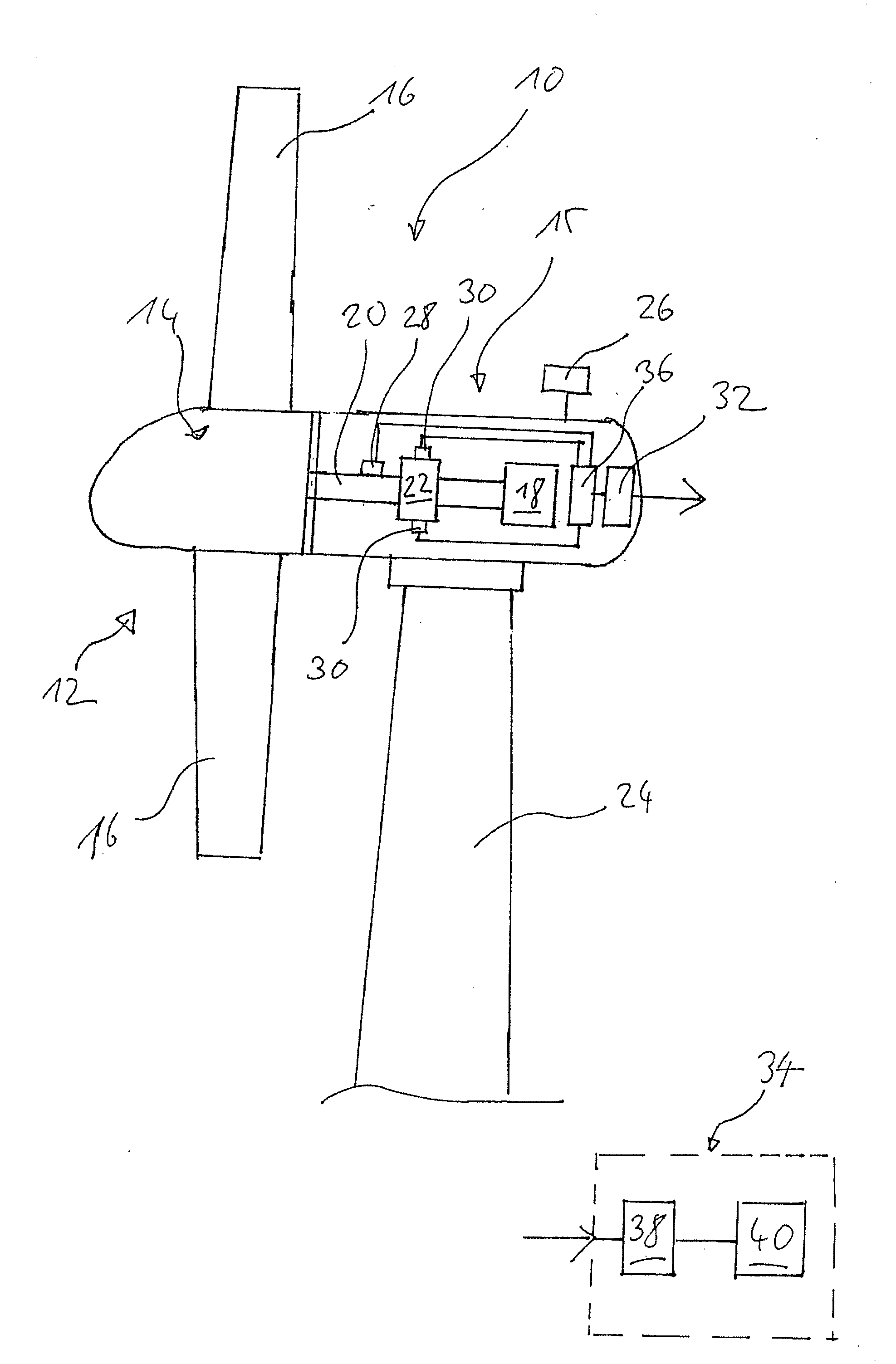
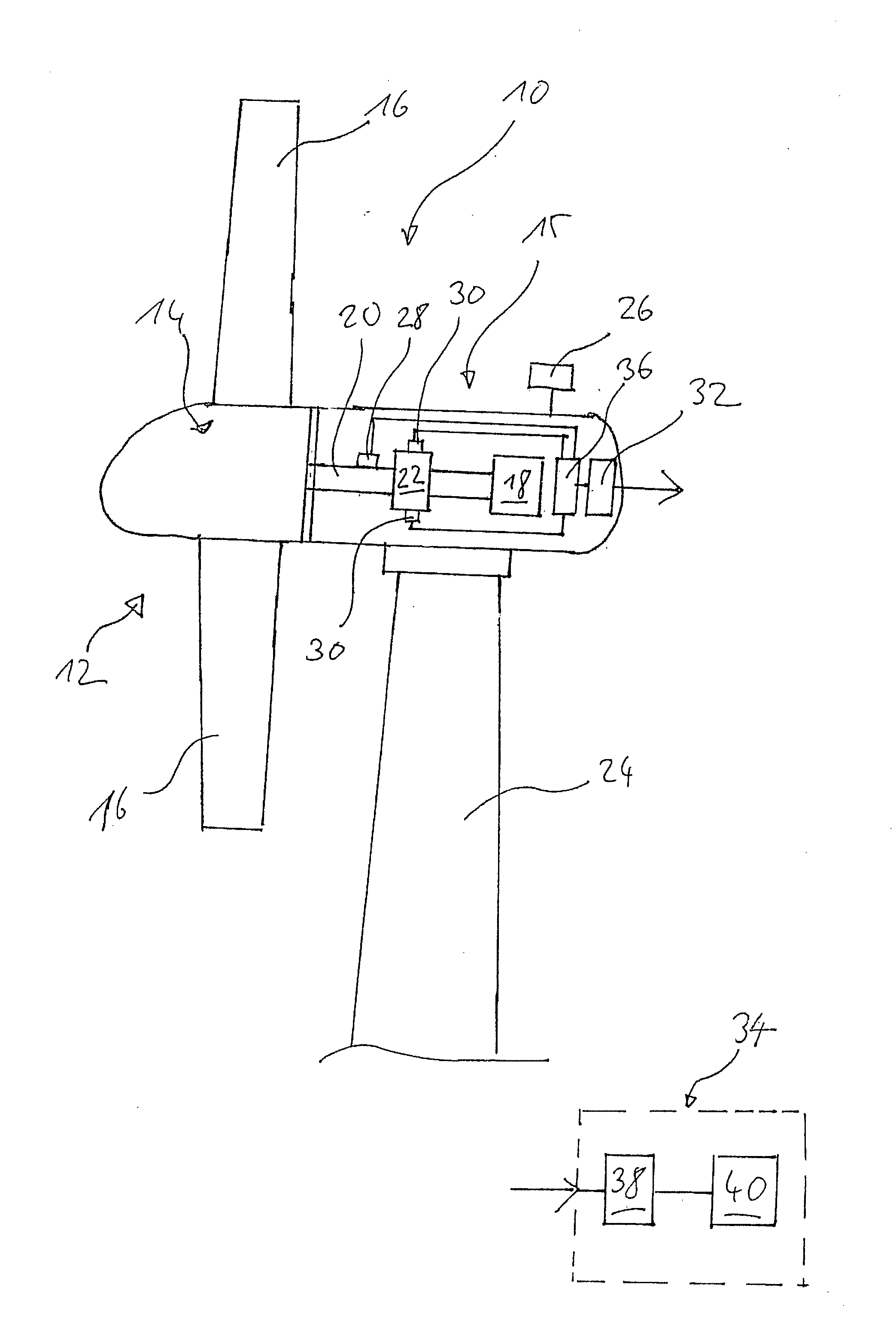
[0016]The sole figure shows an example of a wind power plant 10. Here, there is a rotor 12 with a hub 14 for three rotor blades 16 (of which only 2 are shown in FIG. 1). The rotor 12 is supported in a horizontal alignment in a gondola 15 which houses a generator 18 which is driven by the rotor shaft 20 by way of a transmission 22. The gondola 15 is pivoted around a vertical axis on a tower 24, and furthermore, has a sensor 26 for the wind speed and the wind direction. Moreover, there is a sensor 28 for detecting the rpm of the rotor 12. The rotor blades 16 are each adjustable by means of blade setting mechanism (not shown) around their lengthwise axis with respect to the hub 14 in order to set the pitch of the rotor blades 16 in the conventional manner.

[0017]Several vibration sensors 30 are attached to the transmission 22. These vibration sensors 30 can be attached, for example, axially or radially to the planetary gearing, the main bearing or to the bearing of the output shaft to t...


PUM


Abstract

A process for monitoring a drive train component (22) of a wind power plant (10) with a rotor (12), the rotor rpm being detected, the wind power plant being controlled such that the rotor rpm rises during an acceleration phase, during the acceleration phase vibration signals being detected by at least one vibration sensor (30) attached to the drive train component in order to detect vibration spectra at different rotor rpm, and the vibration spectra detected at different rotor rpm being displayed as a superposition spectrum in order to evaluate the state of the drive train component.

Description

BACKGROUND OF THE INVENTION[0001]1. Field of Invention[0002]This invention relates to a process for monitoring a drive train component of a wind power plant.[0003]2. Description of Related Art[0004]In general, it is a known procedure in mechanical engineering to record so-called coasting curves for system diagnosis, a vibration sensor being attached at a suitable location on the system and the machine being accelerated until the setpoint rpm is exceeded. From this rpm, which is somewhat above the setpoint rpm, the rpm is then reduced to the setpoint, during this so-called coasting phase during which the rpm is reduced, a vibration spectrum is recorded. It is likewise possible to allow the machine to run from rated operation to stoppage for the coasting phase.[0005]In wind power plants, it has now been shown that it is not especially helpful for diagnosis to record these coasting curves. First of all, it is not easily possible to set an rpm above the rated rpm at all, since the maxim...

Claims


Application Information

Patent Timeline
IPC IPC(8): G01M13/02F03D7/02G01H1/00
CPCF03D7/0276F03D11/0091F05B2260/80Y02E10/722F05B2270/334Y02E10/723F05B2270/327F03D17/00Y02E10/72
Inventor BECKER, EDWIN
Owner PRUTECHNIK DIETER BUSCH AG
Learn More