Method and apparatus for communications accelerator on cip motion networks

a technology of cip motion network and accelerator, which is applied in the direction of instruments, digital computers, computing, etc., can solve the problems of high cost of solution, high computational burden of host cpu, and inability to meet the motion i/o connection processing time requirements of distributed device processors that have to perform other control processes (e.g., motor control), so as to speed up cip communication and reduce computational burden on the host cpu , the effect of accelerating communication processes

Active Publication Date: 2010-04-01
ROCKWELL AUTOMATION TECH
View PDF22 Cites 7 Cited by
  • Summary
  • Abstract
  • Description
  • Claims
  • Application Information

AI Technical Summary

Benefits of technology

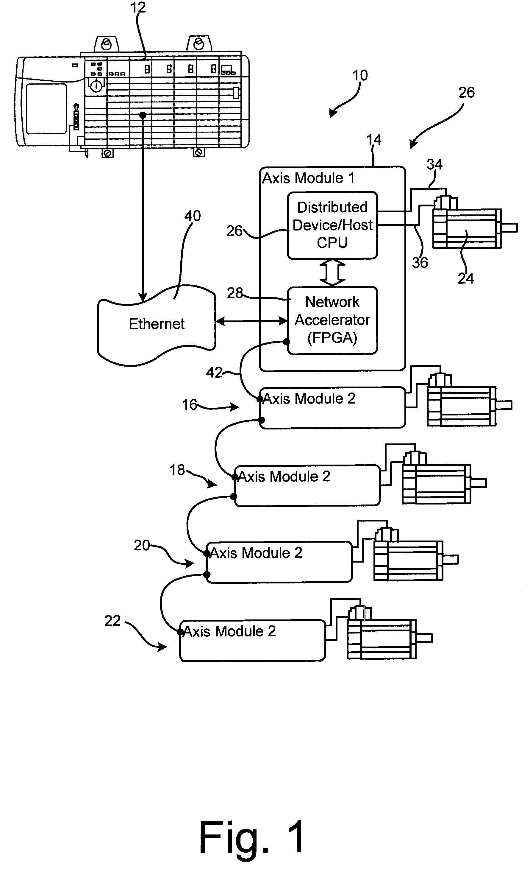
[0019]It has been recognized that the software stack that is typically maintained by a motion drive CPU may instead be implemented in a hardware based network accelerator that includes its own processor to speed up CIP communications between a motion controller and a motion drive. Here, the accelerator can receive Ethernet/IP packets, parse the packets to access CIP data, parse the CIP data to generate application data, store the application data in mailboxes accessible by a host CPU and then provide interrupts to the host CPU to indicate that data is waiting for the CPU in th

Problems solved by technology

While PLCs typically have plenty of processing power to handle communication tasks (i.e., packing and unpacking command data, informational data, etc.) within required processing times and still perform other required functions, unfortunately, tests have shown that distributed device processors that have to perform other control processes (e.g., motor control) often fail to meet the motion I/O connection processing time requirements.
First, this solution would be particularly expensive as higher performance processors having L2 cache are generally more expensive than existing processors that have L1 cache.
Additional overall system expense could render these types of systems unsuitable for certain applications.
Second, device processor suppliers may view EtherNet/IP as an evolving technology and

Method used


Image

  • Method and apparatus for communications accelerator on cip motion networks
  • Method and apparatus for communications accelerator on cip motion networks
  • Method and apparatus for communications accelerator on cip motion networks

Examples


Embodiment Construction

[0039]The various aspects of the subject disclosure are now described with reference to the annexed drawings, wherein like numerals refer to like or corresponding elements throughout. It should be understood, however, that the drawings and detailed description relating thereto are not intended to limit the claimed subject matter to the particular form disclosed. Rather, the intention is to cover all modifications, equivalents, and alternatives falling within the spirit and scope of the claimed subject matter.

[0040]As used herein, the terms “component,”“system” and the like are intended to refer to a computer-related entity, either hardware, a combination of hardware and software, software, or software in execution. For example, a component may be, but is not limited to being, a process running on a processor, a processor, an object, an executable, a thread of execution, a program, and / or a computer. By way of illustration, both an application running on computer and the computer can...


PUM


Abstract

An apparatus for accelerating communications over the Ethernet between a first processor and a second processor where the communications include CIP messages, the apparatus comprising a network accelerator that includes memory locations, the accelerator associated with the first processor and programmed to, when the second processor transmits a data packet to the first processor over the Ethernet, intercept the data packet at a first processor end of the Ethernet, extract a CIP message from the data packet, parse the CIP message to generate received data, store the received data in the memory locations and provide a signal to the first processor indicating that data for the first processor in stored in the memory locations.

Description

CROSS-REFERENCE TO RELATED APPLICATIONS[0001]Not applicable.STATEMENT REGARDING FEDERALLY SPONSORED RESEARCH OR DEVELOPMENT[0002]Not applicable.BACKGROUND OF THE INVENTION[0003]The present invention relates to methods and apparatus for accelerating communication processes in industrial controls and more specifically to methods and apparatus for substantially reducing the time required to process common industrial protocol (CIP) network communications in motion control applications.[0004]Industrial programmable logic controllers (PLCs) are special purpose processing devices used for controlling / monitoring automated and semi-automated industrial processes, machines, manufacturing equipment, plants, and the like. A typical PLC executes a control program or routine in order to track process variables or inputs representative of the status of controlled processes / machines and to generate outputs for controlling the processes / machines.[0005]In distributed control systems, the process cont...

Claims


Application Information

Patent Timeline
IPC IPC(8): G06F15/173
CPCH04L69/161H04L69/16
Inventor RELANDER, RANDI J.GURU, ARUN K.
Owner ROCKWELL AUTOMATION TECH
Why Eureka
Try Eureka